Nissan Pathfinder. Manual - part 713
POWER SUPPLY AND GROUND CIRCUIT
HAC-113
< DTC/CIRCUIT DIAGNOSIS >
[AUTOMATIC AIR CONDITIONING]
C
D
E
F
G
H
J
K
L
M
A
B
HAC
N
O
P
Is the inspection result normal?
YES
>> GO TO 2.
NO
>> GO TO 4.
2.
CHECK AIR MIX DOOR MOTOR (DRIVER SIDE) GROUND CIRCUIT
1. Turn ignition switch OFF.
2. Disconnect air mix door motor (driver side) connector.
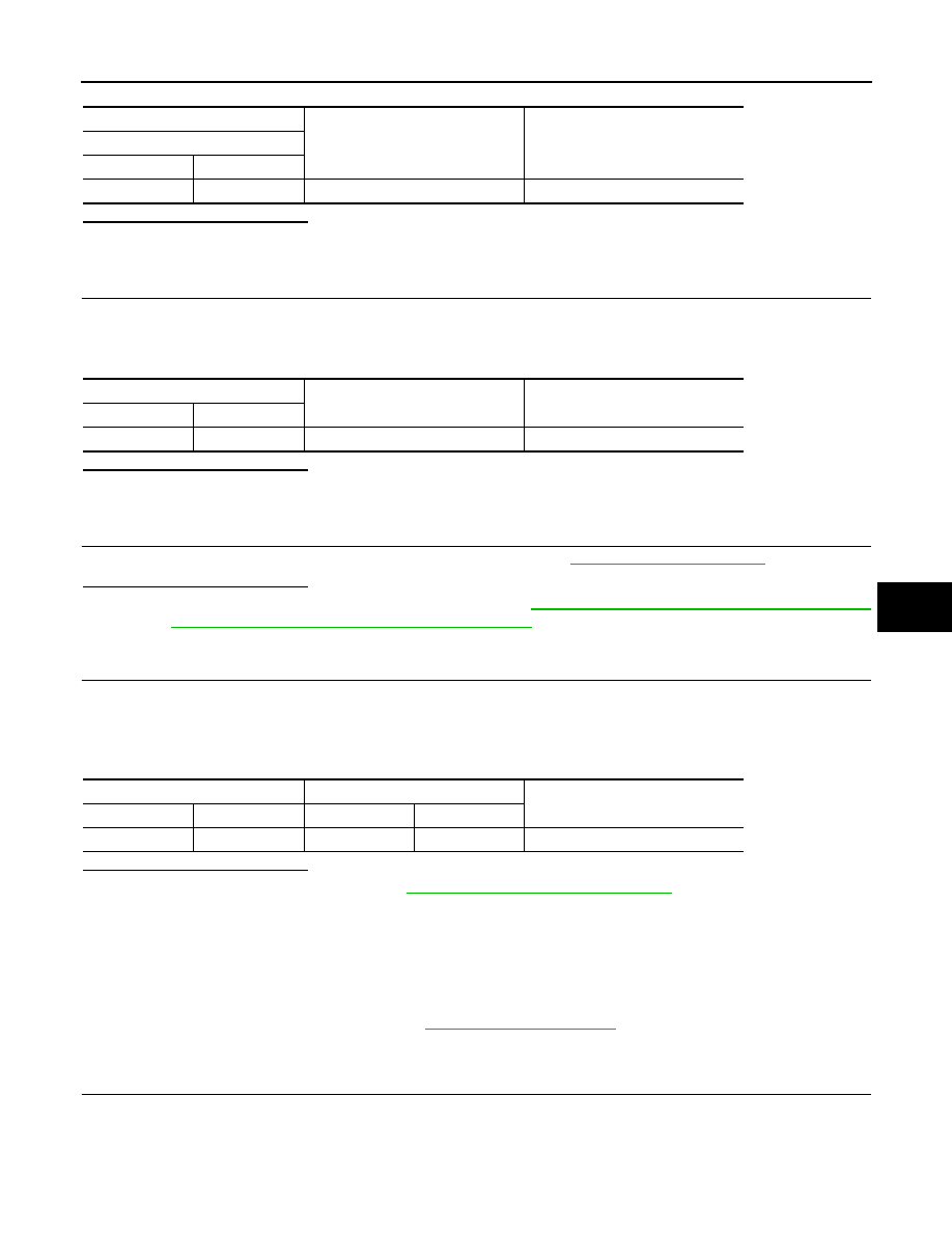
3. Check continuity between air mix door motor (driver side) harness connector and ground.
Is the inspection result normal?
YES
>> GO TO 3.
NO
>> Repair harness or connector.
3.
CHECK INSTALLATION OF AIR MIX DOOR MOTOR (DRIVER SIDE)
Check air mix door motor (driver side) is properly installed. Refer to
.
Is the inspection result normal?
YES
>> Replace air mix door motor (driver side). Refer to
HAC-165, "AIR MIX DOOR MOTOR : Removal
and Installation - Air Mix Door Motor (Driver Side)"
.
NO
>> Repair or replace malfunctioning part.
4.
CHECK AIR MIX DOOR MOTOR (DRIVER SIDE) POWER SUPPLY CIRCUIT
1. Turn ignition switch OFF.
2. Disconnect air mix door motor (driver side) connector and A/C auto amp. connector.
3. Check continuity between air mix door motor (driver side) harness connector and A/C auto amp. harness
connector.
Is the inspection result normal?
YES
>> Replace A/C auto amp. Refer to
HAC-157, "Removal and Installation"
.
NO
>> Repair harness or connector.
AIR MIX DOOR MOTOR (PASSENGER SIDE)
AIR MIX DOOR MOTOR (PASSENGER SIDE) : Diagnosis Procedure
INFOID:0000000009176853
Regarding Wiring Diagram information, refer to
1.
CHECK AIR MIX DOOR MOTOR (PASSENGER SIDE) POWER SUPPLY
1. Turn ignition switch ON.
2. Check voltage between air mix door motor (passenger side) harness connector and ground.
+
−
Voltage
(Approx.)
Air mix door motor (driver side)
Connector
Terminal
M130
1
Ground
Battery voltage
Air mix door motor (driver side)
—
Continuity
Connector
Terminal
M130
3
Ground
Yes
Air mix door motor (driver side)
A/C auto amp.
Continuity
Connector
Terminal
Connector
Terminal
M130
1
M50
17
Yes