Nissan Pathfinder. Manual - part 608


  Index      Nissan     Nissan Pathfinder (2014 year) - Service and Repair Manual


Search            


Content   ..  606  607  608  609   ..


Nissan Pathfinder. Manual - part 608


EXL-120

< DTC/CIRCUIT DIAGNOSIS >

PARKING LAMP CIRCUIT

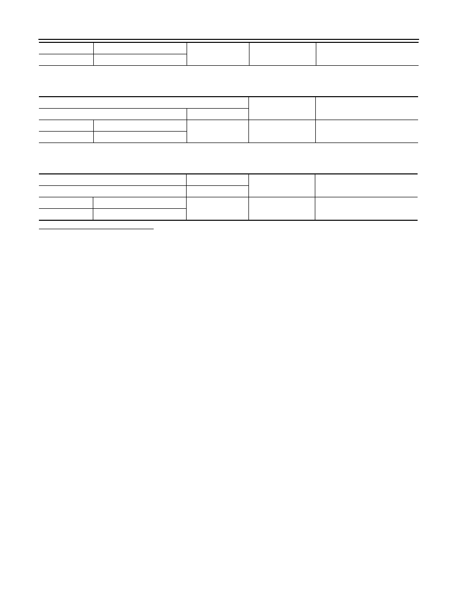
5. Check continuity between the rear combination lamp (side marker) harness connector and ground.

6. Check continuity between the license plate lamp harness connector and ground.

Are the inspection result normal?

YES

>> Inspect the parking, side marker or license plate lamp bulb.

NO

>> Repair or replace the harness or connector.

LH

B406

2

Ground

Yes

RH

B407

Rear combination lamp (side marker)

(

−)

Continuity

Connector

Terminal

LH

B412

7

Ground

Yes

RH

B413

License plate lamp

(

−)

Continuity

Connector

Terminal

LH

D561

2

Ground

Yes

RH

D562

TURN SIGNAL LAMP CIRCUIT

EXL-121

< DTC/CIRCUIT DIAGNOSIS >

C

D

E

F

G

H

I

J

K

M

A

B

EXL

N

O

P

TURN SIGNAL LAMP CIRCUIT

Description

INFOID:0000000009175380

The BCM monitors inputs from the combination switch (lighting and turn signal switch) to determine when to

activate the turn signals. The BCM outputs voltage to the left and right turn signals during turn signal operation

or both during hazard warning operation. The BCM sends a turn signal indicator request to the combination

meter via the CAN communication lines. 

The BCM performs the fast flasher operation (fail-safe) if any bulb or harness of the turn signal lamp circuit is

open.

NOTE:

Turn signal lamp blinks at normal speed when using the hazard warning lamp.

Component Function Check

INFOID:0000000009175381

1.

CHECK TURN SIGNAL LAMP

CONSULT 

1. Select FLASHER of BCM (FLASHER) active test item.

2. While operating the test items, check that the turn signal lamp blinks.

Is the inspection result normal?

YES

>> Turn signal lamp circuit is normal.

NO

>> Refer to 

EXL-121, "Diagnosis Procedure"

.

Diagnosis Procedure

INFOID:0000000009175382

Regarding Wiring Diagram information, refer to 

EXL-56, "Wiring Diagram"

.

1.

CHECK TURN SIGNAL LAMP BULB

Check the applicable lamp bulb to be sure the proper bulb standard is in use and the bulb is not open.
Is the inspection result normal?

YES

>> GO TO 2.

NO

>> Replace the bulb.

2.

CHECK TURN SIGNAL LAMP OUTPUT VOLTAGE

1. Turn the ignition switch OFF.

2. Disconnect the front or rear combination lamp harness connector in question.

3. Turn the ignition switch ON.

4. Operate the turn signal switch.

5. While the turn signal is operating, check the voltage between the front combination lamp harness connec-

tor and ground.

LH

: Turn signal lamps (LH) ON

RH

: Turn signal lamps (RH) ON

Off

: Turn signal lamps OFF

(+)

(

−)

Voltage

(Approx.)

Connector

Terminal

EXL-122

< DTC/CIRCUIT DIAGNOSIS >

TURN SIGNAL LAMP CIRCUIT

6. While the turn signal is operating, check the voltage between the rear combination lamp harness connec-

tor and ground.

Is the inspection result normal?

YES

>> GO TO 5.

NO

>> GO TO 3.

3.

CHECK TURN SIGNAL LAMP CIRCUIT FOR OPEN 

1. Turn the ignition switch OFF.

2. Disconnect BCM harness connector M20 or M80.

3. Check continuity between the BCM harness connector M80 and the front combination lamp harness con-

nector.

4. Check continuity between the BCM harness connector M20 and the rear combination lamp harness con-

nector. 

Is the inspection result normal?

YES

>> GO TO 4.

NO

>> Repair or replace the harness or connector.

4.

CHECK TURN SIGNAL LAMP SHORT CIRCUIT 

1. Check continuity between the BCM harness connector M80 and ground.

RH

E239 

5

Ground

LH

E234 

(+)

(

−)

Voltage

(Approx.)

Connector

Terminal

RH

B409 

4

Ground

LH

B408 

PKID0926E

PKID0926E

BCM

Front combination lamp

Continuity

Connector

Terminal

Connector

Terminal

LH

M80

117

E234

5

Yes

RH

105

E239

BCM

Rear combination lamp

Continuity

Connector

Terminal

Connector

Terminal

LH

M20

103

B408

4

Yes

RH

92

B409

TURN SIGNAL LAMP CIRCUIT

EXL-123

< DTC/CIRCUIT DIAGNOSIS >

C

D

E

F

G

H

I

J

K

M

A

B

EXL

N

O

P

2. Check continuity between the BCM harness connector M20 and ground. 

Is the inspection result normal?

YES

>> Replace BCM. Refer to 

BCS-80, "Removal and Installation"

.

NO

>> Repair or replace the harness or connector.

5.

CHECK TURN SIGNAL LAMP GROUND CIRCUIT

1. Turn the ignition switch OFF.

2. Check continuity between the front combination lamp harness connector and ground.

3. Check continuity between the rear combination lamp harness connector and ground.

Is the inspection result normal?

YES

>> Replace the malfunctioning lamp.

NO

>> Repair or replace the harness or connector.

BCM

Ground

Continuity

Connector

Terminal

LH

M80

117

No

RH

105

BCM

Ground

Continuity

Connector

Terminal

LH

M20

103

No

RH

92

Front combination lamp

(

−)

Continuity

Connector

Terminal

LH

E234

6

Ground

Yes

RH

E239

Rear combination lamp

(

−)

Continuity

Connector

Terminal

LH

B408

5

Ground

Yes

RH

B409


Content   ..  606  607  608  609   ..