Nissan Pathfinder. Manual - part 533
EC-438
< DTC/CIRCUIT DIAGNOSIS >
[VQ35DE]
IGNITION SIGNAL
Is the inspection result normal?
YES
>> GO TO 7.
NO
>> Repair or replace harness or connectors.
7.
CHECK IGNITION COIL GROUND CIRCUIT FOR OPEN AND SHORT
1. Turn ignition switch OFF.
2. Check the continuity between ignition coil harness connector and ground.
3. Also check harness for short to power.
Is the inspection result normal?
YES
>> GO TO 8.
NO
>> Repair open circuit or short to power in harness or connectors.
8.
CHECK IGNITION COIL OUTPUT SIGNAL CIRCUIT FOR OPEN AND SHORT
1. Disconnect ECM harness connector.
2. Check the continuity between ignition coil harness connector and ECM harness connector.
3. Also check harness for short to ground and short to power.
Is the inspection result normal?
YES
>> GO TO 9.
NO
>> Repair open circuit, short to ground or short to power in harness or connectors.
9.
CHECK IGNITION COIL WITH POWER TRANSISTOR
Check ignition coil with power transistor. Refer to
EC-440, "Component Inspection (Ignition Coil with Power
.
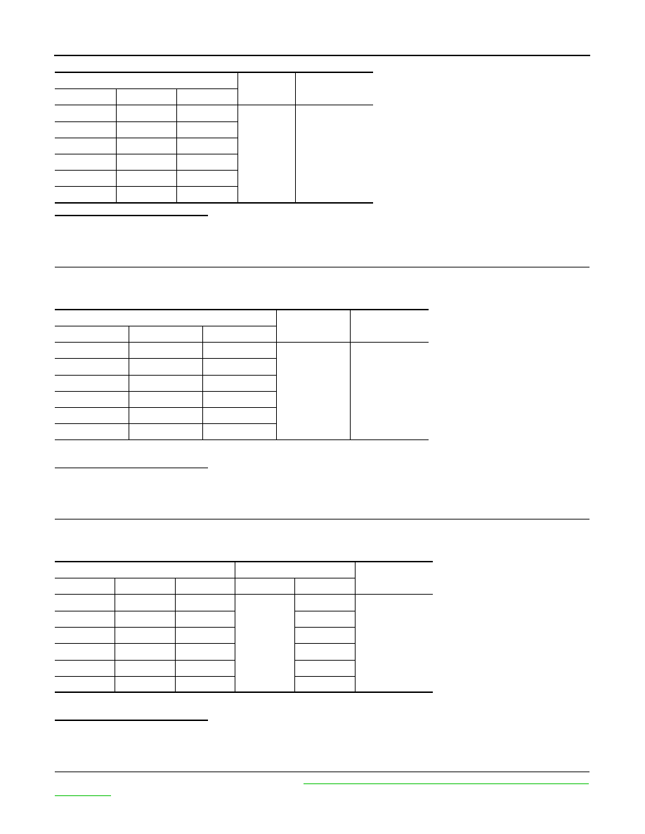
Ignition coil
Ground
Voltage
Cylinder
Connector
Terminal
1
F47
3
Ground
Battery voltage
2
F8
3
3
F48
3
4
F9
3
5
F49
3
6
F10
3
Ignition coil
Ground
Continuity
Cylinder
Connector
Terminal
1
F47
2
Ground
Existed
2
F8
2
3
F48
2
4
F9
2
5
F49
2
6
F10
2
Ignition coil
ECM
Continuity
Cylinder
Connector
Terminal
Connector
Terminal
1
F47
1
F51
11
Existed
2
F8
1
10
3
F48
1
9
4
F9
1
15
5
F49
1
14
6
F10
1
13