Nissan Pathfinder. Manual - part 430


  Index      Nissan     Nissan Pathfinder (2014 year) - Service and Repair Manual


Search            


Content   ..  428  429  430  431   ..


Nissan Pathfinder. Manual - part 430


EC-26

< SYSTEM DESCRIPTION >

[VQ35DE]

COMPONENT PARTS

Knock Sensor

INFOID:0000000009178025

The knock sensor is attached to the cylinder block. It senses engine

knocking using a piezoelectric element. A knocking vibration from

the cylinder block is sensed as vibrational pressure. This pressure is

converted into a voltage signal and sent to the ECM.

Malfunction Indicator Lamp (MIL)

INFOID:0000000009178026

Malfunction Indicator lamp (MIL) is located on the combination

meter.

MIL will illuminate when the ignition switch is turned ON without the

engine running. This is a bulb check.

When the engine is started, MIL should turn OFF. If the MIL remains

illuminated, the on board diagnostic system has detected an engine

system malfunction.

For details, refer to 

EC-58, "DIAGNOSIS DESCRIPTION : Malfunc-

tion Indicator Lamp (MIL)"

.

Mass Air Flow Sensor (With Intake Air Temperature Sensor)

INFOID:0000000009178027

MASS AIR FLOW SENSOR

The mass air flow sensor   is placed in the stream of intake air. It

measures the intake flow rate by measuring a part of the entire

intake flow. The mass air flow sensor controls the temperature of the

hot wire to a certain amount. The heat generated by the hot wire is

reduced as the intake air flows around it. The more air, the greater

the heat loss. 

Therefore, the electric current supplied to hot wire is changed to

maintain the temperature of the hot wire as air flow increases. The

ECM detects the air flow by means of this current change.

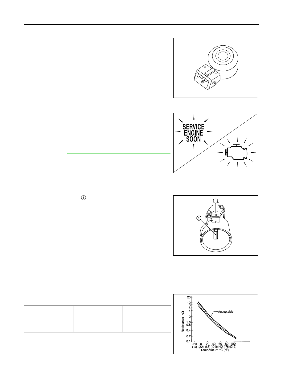
INTAKE AIR TEMPERATURE SENSOR

The intake air temperature sensor is built-into mass air flow sensor. The sensor detects intake air temperature

and transmits a signal to the ECM.

The temperature sensing unit uses a thermistor which is sensitive to the change in temperature. Electrical

resistance of the thermistor decreases in response to the temperature rise.

<Reference data>

*: These data are reference values and are measured between ECM terminals.

JSBIA0284ZZ

JSBIA1315ZZ

PBIA9559J

Intake air temperature

[

°C (°F)]

Voltage

*

 (V)

Resistance (k

Ω)

25 (77)

3.3

1.800 - 2.200

80 (176)

1.2

0.283 - 0.359

SEF012P

COMPONENT PARTS

EC-27

< SYSTEM DESCRIPTION >

[VQ35DE]

C

D

E

F

G

H

I

J

K

L

M

A

EC

N

P

O

Oil Pressure Warning Lamp

INFOID:0000000009178028

Oil pressure warning lamp is located on the combination meter. 

It indicates the low pressure of the engine oil and the malfunction of

the engine oil pressure system.

Combination meter turns the oil pressure warning lamp ON/OFF

according to the oil pressure warning lamp signal received from

ECM via CAN communication.

For details, refer to 

EC-43, "ENGINE PROTECTION CONTROL AT

LOW ENGINE OIL PRESSURE : System Description"

.

Power Valve Actuator 1 and 2

INFOID:0000000009178029

The power valves are used to control the suction passage of the variable induction air control system. They

are set in the fully closed or fully opened position by the power valve actuators operated by the vacuum stored

in the vacuum tank. The vacuum to power valve actuators is controlled by the VIAS control solenoid valves.

Refrigerant Pressure Sensor

INFOID:0000000009178030

The refrigerant pressure sensor is installed at the condenser of the air conditioner system. The sensor uses an

electrostatic volume pressure transducer to convert refrigerant pressure to voltage. The voltage signal is sent

to ECM, and ECM controls cooling fan system.

Stop Lamp Switch & Brake Pedal Position Switch

INFOID:0000000009178031

Stop lamp switch and brake pedal position switch are installed to brake pedal bracket.

ECM detects the state of the brake pedal by those two types of input (ON/OFF signal).

VIAS Control Solenoid Valve 1 and 2

INFOID:0000000009178032

The VIAS control solenoid valve cuts the intake manifold vacuum signal for power valve control. It responds to

ON/OFF signals from the ECM. When the solenoid is OFF, the vacuum signal from the intake manifold is cut.

When the ECM sends an ON signal the coil pulls the plunger downward and sends the vacuum signal to the

power valve actuator.

PBIA8559J

PBIB2657E

Brake pedal

Brake pedal position switch

Stop lamp switch

Released

ON

OFF

Depressed

OFF

ON

EC-28

< SYSTEM DESCRIPTION >

[VQ35DE]

STRUCTURE AND OPERATION

STRUCTURE AND OPERATION

Positive Crankcase Ventilation (PCV)

INFOID:0000000009178033

This system returns blow-by gas to the intake manifold.

The positive crankcase ventilation (PCV) valve is provided to conduct crankcase blow-by gas to the intake

manifold.

During partial throttle operation of the engine, the intake manifold sucks the blow-by gas through the PCV

valve.

Normally, the capacity of the valve is sufficient to handle any blow-by and a small amount of ventilating air.

The ventilating air is drawn from the air inlet tubes into the crankcase. In this process the air passes through

the hose connecting air inlet tubes to rocker cover.

Under full-throttle condition, the manifold vacuum is insufficient to draw the blow-by flow through the valve.

The flow goes through the hose connection in the reverse direction.

On vehicles with an excessively high blow-by, the valve does not

meet the requirement. This is because some of the flow will go

through the hose connection to the air inlet tubes under all condi-

tions.

SEC921C

PBIB1588E

STRUCTURE AND OPERATION

EC-29

< SYSTEM DESCRIPTION >

[VQ35DE]

C

D

E

F

G

H

I

J

K

L

M

A

EC

N

P

O

On Board Refueling Vapor Recovery (ORVR)

INFOID:0000000009178034

From the beginning of refueling, the air and vapor inside the fuel tank go through refueling EVAP vapor cut

valve and EVAP/ORVR line to the EVAP canister. The vapor is absorbed by the EVAP canister and the air is

released to the atmosphere.

When the refueling has reached the full level of the fuel tank, the refueling EVAP vapor cut valve is closed and

refueling is stopped because of auto shut-off. The vapor which was absorbed by the EVAP canister is purged

during driving.

WARNING:

When conducting inspections below, be sure to observe the following:

• Put a “CAUTION: FLAMMABLE” sign in workshop.

• Never smoke while servicing fuel system. Keep open flames and sparks away from work area.

• Always to furnish the workshop with a CO

2

 fire extinguisher.

CAUTION:

• Before removing fuel line parts, carry out the following procedures:

- Put drained fuel in an explosion-proof container and put lid on securely.

- Release fuel pressure from fuel line. Refer to 

EC-151, "Work Procedure"

.

- Disconnect battery ground cable.

• Always replace O-ring when the fuel gauge retainer is removed.

• Never kink or twist hose and tube when they are installed.

• Never tighten hose and clamps excessively to avoid damaging hoses.

• After installation, run engine and check for fuel leakage at connections.

• Never attempt to top off the fuel tank after the fuel pump nozzle shuts off automatically.

Continued refueling may cause fuel overflow, resulting in fuel spray and possibly a fire.

PBIB1068E


Content   ..  428  429  430  431   ..