Nissan Pathfinder. Manual - part 429


  Index      Nissan     Nissan Pathfinder (2014 year) - Service and Repair Manual


Search            


Content   ..  427  428  429  430   ..


Nissan Pathfinder. Manual - part 429


EC-22

< SYSTEM DESCRIPTION >

[VQ35DE]

COMPONENT PARTS

In the driving range, ECM turns ON the electronically-controlled engine mount control solenoid valve and cuts

manifold pressure applied on the electronically-controlled engine mount. This increases damping force of the

electronically-controlled engine mount and reduces vibrations generated during driving.

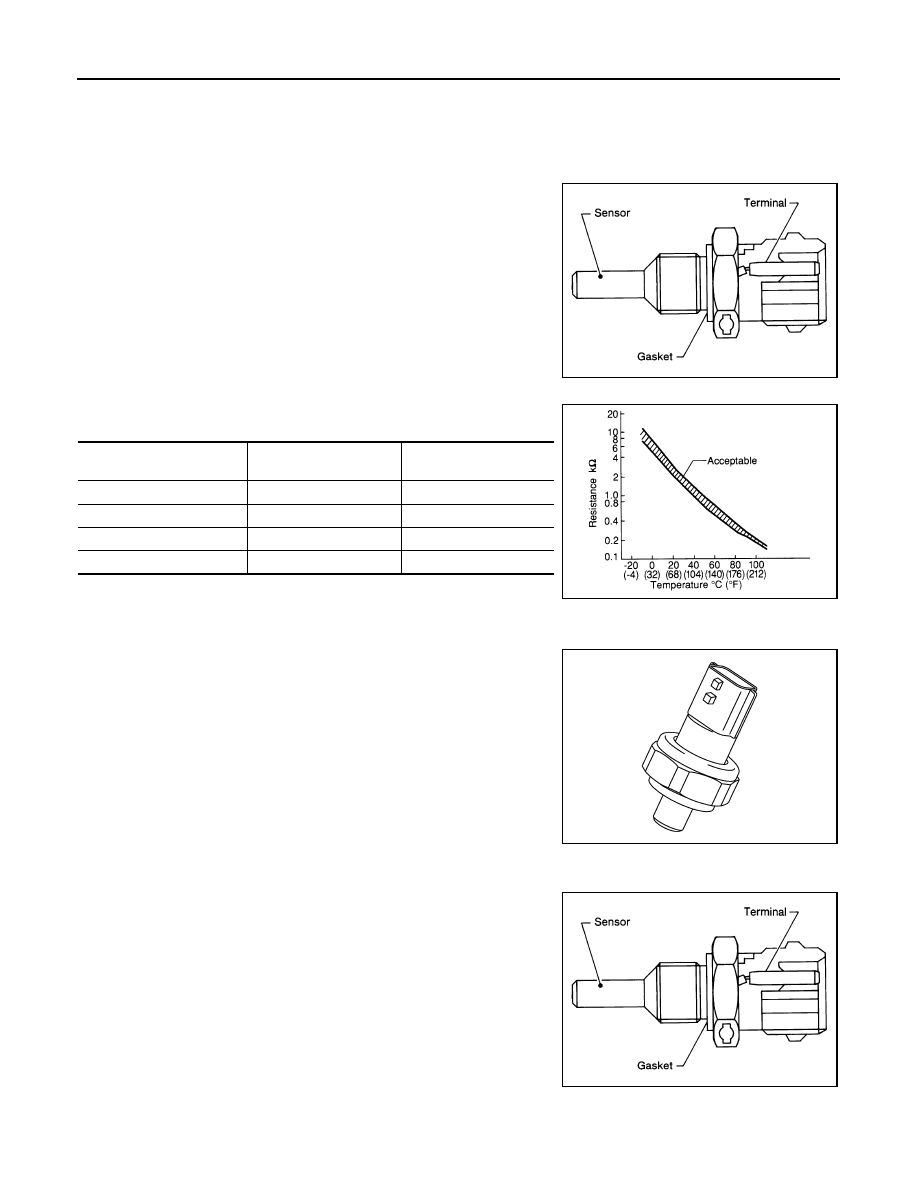
Engine Coolant Temperature Sensor

INFOID:0000000009178013

The engine coolant temperature sensor is used to detect the engine

coolant temperature. The sensor modifies a voltage signal from the

ECM. The modified signal returns to the ECM as the engine coolant

temperature input. The sensor uses a thermistor which is sensitive to

the change in temperature. The electrical resistance of the ther-

mistor decreases as temperature increases.

<Reference data>

*: These data are reference values and are measured between ECM terminals.

Engine Oil Pressure Sensor

INFOID:0000000009178014

The engine oil pressure (EOP) sensor is detects engine oil pressure

and transmits a voltage signal to the ECM.

Engine Oil Temperature Sensor

INFOID:0000000009178015

The engine oil temperature sensor is used to detect the engine oil

temperature. The sensor modifies a voltage signal from the ECM.

The modified signal returns to the ECM as the engine oil tempera-

ture input. The sensor uses a thermistor which is sensitive to the

change in temperature. The electrical resistance of the thermistor

decreases as temperature increases.

SEF594K

Engine coolant temperature

[

°C (°F)]

Voltage

*

 (V)

Resistance (k

Ω)

–10 (14)

4.4

7.0 - 11.4

20 (68)

3.5

2.37 - 2.63

50 (122)

2.2

0.68 - 1.00

90 (194)

0.9

0.236 - 0.260

SEF012P

JSBIA0292ZZ

SEF594K

COMPONENT PARTS

EC-23

< SYSTEM DESCRIPTION >

[VQ35DE]

C

D

E

F

G

H

I

J

K

L

M

A

EC

N

P

O

<Reference data>

*: These data are reference values and are measured between ECM terminals.

EVAP Canister

INFOID:0000000009178016

The fuel vapor in the sealed fuel tank is led into the EVAP canister which contains activated carbon and the

vapor is stored there when the engine is not operating or when refueling to the fuel tank.

For details, refer to 

EC-41, "EVAPORATIVE EMISSION SYSTEM : System Description"

.

EVAP Canister Purge Volume Control Solenoid Valve

INFOID:0000000009178017

The EVAP canister purge volume control solenoid valve is used to

control the flow rate of fuel vapor from the EVAP canister. The EVAP

canister purge volume control solenoid valve is moved by ON/OFF

pulses from the ECM. The longer the ON pulse, the greater the

amount of fuel vapor that will flow through the valve.

EVAP Canister Vent Control Valve

INFOID:0000000009178018

The EVAP canister vent control valve is located on the EVAP canis-

ter and is used to seal the canister vent.

This solenoid valve responds to signals from the ECM. When the

ECM sends an ON signal, the coil in the solenoid valve is energized.

A plunger will then move to seal the canister vent. The ability to seal

the vent is necessary for the on board diagnosis of other evaporative

emission control system components.

This solenoid valve is used only for diagnosis, and usually remains

opened.

When the vent is closed, under normal purge conditions, the evapo-

rative emission control system is depressurized and allows “EVAP

Control System” diagnosis.

EVAP Control System Pressure Sensor

INFOID:0000000009178019

The EVAP control system pressure sensor detects pressure in the

purge line. The sensor output voltage to the ECM increases as pres-

sure increases.

Engine oil temperature

[

°C (°F)]

Voltage

*

 (V)

Resistance (k

Ω)

–10 (14)

4.4

7.0 - 11.4

20 (68)

3.5

2.37 - 2.63

50 (122)

2.2

0.68 - 1.00

90 (194)

0.9

0.236 - 0.260

110 (230)

0.6

0.143 - 0.153

SEF012P

PBIB3489E

JSBIA1337GB

PBIB3370E

EC-24

< SYSTEM DESCRIPTION >

[VQ35DE]

COMPONENT PARTS

Fuel Injector

INFOID:0000000009178020

The fuel injector is a small, precise solenoid valve. When the ECM

supplies a ground to the fuel injector circuit, the coil in the fuel injec-

tor is energized. The energized coil pulls the ball valve back and

allows fuel to flow through the fuel injector into the intake manifold.

The amount of fuel injected depends upon the injection pulse dura-

tion. Pulse duration is the length of time the fuel injector remains

open. The ECM controls the injection pulse duration based on

engine fuel needs.

Fuel Level Sensor Unit and Fuel Pump (With Fuel Tank Temperature Sensor)

INFOID:0000000009178021

FUEL PUMP

The ECM activates the fuel pump for 1 second after the ignition

switch is turned ON to improve engine start ability. If the ECM

receives an engine speed signal from the camshaft position sensor

(PHASE), it knows that the engine is rotating, and causes the pump

to operate. If the engine speed signal is not received when the igni-

tion switch is ON, the engine stalls. The ECM stops pump operation

and prevents battery discharging, thereby improving safety. The

ECM does not directly drive the fuel pump. It sends the control signal

to the fuel pump control module, which in turn controls the fuel

pump.

FUEL LEVEL SENSOR

The fuel level sensor is mounted in the fuel level sensor unit.

The sensor detects a fuel level in the fuel tank and transmits a signal to the combination meter. The combina-

tion meter sends the fuel level sensor signal to the ECM via the CAN communication line.

It consists of two parts, one is mechanical float and the other is variable resistor. Fuel level sensor output volt-

age changes depending on the movement of the fuel mechanical float.

FUEL TANK TEMPERATURE SENSOR

The fuel tank temperature sensor is used to detect the fuel tempera-

ture inside the fuel tank. The sensor modifies a voltage signal from

the ECM. The modified signal returns to the ECM as the fuel temper-

ature input. The sensor uses a thermistor which is sensitive to the

change in temperature. The electrical resistance of the thermistor

decreases as temperature increases.

<Reference data>

*: These data are reference values and are measured between ECM terminals 95 (Fuel tank temperature sensor) and ground.

PBIA9664J

JSBIA1282ZZ

Condition

Fuel pump operation

Ignition switch is turned to ON.

Operates for 1 second.

Engine running and cranking

Operates.

When engine is stopped

Stops in 1.5 seconds.

Except as shown above

Stops.

Fluid temperature

[

°C (°F)]

Voltage*

(V)

Resistance

(k

Ω)

20 (68)

3.5

2.3 - 2.7

50 (122)

2.2

0.79 - 0.90

SEF012P

COMPONENT PARTS

EC-25

< SYSTEM DESCRIPTION >

[VQ35DE]

C

D

E

F

G

H

I

J

K

L

M

A

EC

N

P

O

Heated Oxygen Sensor 2

INFOID:0000000009178022

DESCRIPTION

The heated oxygen sensor 2, after three way catalyst (manifold),

monitors the oxygen level in the exhaust gas.

Even if switching characteristics of the air fuel ratio (A/F) sensor 1

are shifted, the air fuel ratio is controlled to stoichiometric, by the sig-

nal from the heated oxygen sensor 2.

This sensor is made of ceramic zirconia. The zirconia generates volt-

age from approximately 1 V in richer conditions to 0 V in leaner con-

ditions.

Under normal conditions the heated oxygen sensor 2 is not used for

engine control operation.

HEATED OXYGEN SENSOR 2 HEATER

Heated oxygen sensor 2 heater is integrated in the sensor.

The ECM performs ON/OFF control of the heated oxygen sensor 2 heater corresponding to the engine speed,

amount of intake air and engine coolant temperature. 

Ignition Coil (With Power Transistor)

INFOID:0000000009178023

The ignition signal from the ECM is sent to and amplified by the

power transistor. The power transistor turns ON and OFF the ignition

coil primary circuit. This ON/OFF operation induces the proper high

voltage in the coil secondary circuit.

Intake Valve Timing Control Solenoid Valve

INFOID:0000000009178024

Intake valve timing control solenoid valve is activated by ON/OFF

pulse duty (ratio) signals from the ECM.

The intake valve timing control solenoid valve changes the oil

amount and direction of flow through intake valve timing control unit

or stops oil flow.

The longer pulse width advances valve angle.

The shorter pulse width retards valve angle.

When ON and OFF pulse widths become equal, the solenoid valve

stops oil pressure flow to fix the intake valve angle at the control

position.

SEF327R

Engine speed

Heated oxygen sensor 2 heater

Above 3,600 rpm

OFF

Below 3,600 rpm after the following conditions are met.
• Engine: After warming up
• Keeping the engine speed between 3,500 and 4,000 rpm for 1 

minute and at idle for 1 minute under no load

ON

JPBIA4613ZZ

PBIB1842E


Content   ..  427  428  429  430   ..