Nissan Pathfinder. Manual - part 291


  Index      Nissan     Nissan Pathfinder (2014 year) - Service and Repair Manual


Search            


Content   ..  289  290  291  292   ..


Nissan Pathfinder. Manual - part 291


ENGINE COOLANT

CO-11

< PERIODIC MAINTENANCE >

[VQ35DE]

C

D

E

F

G

H

I

J

K

L

M

A

CO

N

P

O

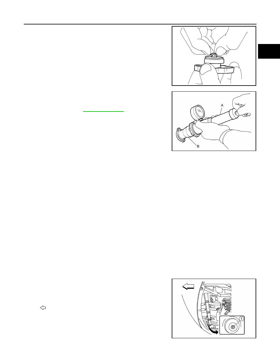
2. Pull the negative-pressure valve to open it and check that it

closes completely when released.

• Check that there is no dirt or damage on the valve seat of the

radiator cap negative-pressure valve. 

• Check that there are no abnormalities in the opening and clos-

ing conditions of the negative-pressure valve.

3. Check radiator cap relief pressure using suitable tool (A) and

(B).

• Apply water or engine coolant to the cap seal surface before

connecting the radiator cap to the tester, 

• Replace the radiator cap if there is an abnormality in the nega-

tive-pressure valve, or if the open-valve pressure is outside of

the standard values.

CHECKING RADIATOR

Check radiator for mud or clogging. If necessary, clean radiator as follows.

CAUTION:

• Be careful not to bend or damage the radiator fins.

• When radiator is cleaned on-vehicle, remove surrounding parts in order to access the radiator core.

Tape the harness and harness connectors to prevent water from entering.

1. Spray water to the back side of the radiator core using a side to side motion from the top down. 
2. Stop spraying when debris no longer flows from radiator core. 
3. Blow air into the back side of radiator core using a side to side motion from the top down.

• Use compressed air lower than 490 kPa (5.00 kg/cm

2

, 71.1 psi) and keep distance more than 30 cm

(11.8 in). 

4. Continue to blow air until no water sprays out.
5. Check for engine coolant leaks. Repair as necessary.

Changing Engine Coolant

INFOID:0000000009177983

WARNING:

Do not remove the radiator cap when the engine is hot. Serious burns could occur from high pressure

engine coolant escaping from the radiator. Wrap a thick cloth around the cap. Slowly turn it a quarter

turn to allow built-up pressure to escape. Carefully remove the cap by turning it all the way.    

DRAINING ENGINE COOLANT

1. Open radiator drain plug (1) at the bottom of radiator and

remove the radiator filler cap. 

CAUTION:

Do not allow the engine coolant to contact the drive belt.

SMA967B

Standard: Refer to 

CO-28, "Radiator"

AWBIA1189GB

: Front

AWBIA1180GB

CO-12

< PERIODIC MAINTENANCE >

[VQ35DE]

ENGINE COOLANT

2. Remove water drain plug (A) and copper sealing washer (B). 

CAUTION:

Do not reuse copper sealing washers.

3. For a complete cooling system drain, remove the reservoir tank and drain the engine coolant, and then

clean the reservoir tank before installation.

CAUTION:

Do not allow the engine coolant to contact the drive belt.

4. When performing a complete cooling system drain, remove the

water drain plug (B), connector bolt (C), and copper sealing

washer (A) on the cylinder block.

CAUTION:

Do not reuse copper sealing washers.

NOTE:

• For Canada, water drain plug (B) is a block heater, not a drain

plug.

• Remove water drain plug (D) and copper sealing washer (E)

during engine overhaul.

CAUTION:

Do not reuse copper sealing washers.

5. Check the drained engine coolant for contaminants such as rust, corrosion or discoloration.

• If contaminated, flush the engine cooling system. Refer to FLUSHING COOLING SYSTEM.

REFILLING ENGINE COOLANT

1. Install the radiator drain plug and the reservoir tank, (if removed).
2. Install the water drain plug (A) and copper sealing washer (B).

Tighten water drain plug to specification. 

CAUTION:

Do not reuse copper sealing washers.

: Engine front

AWBIA1202GB

: Engine front

AWBIA1194GB

: Engine front

Water drain plug (A)

: 12.3 N·m (1.3 kg-m, 9.0 ft-lb)

AWBIA1202GB

ENGINE COOLANT

CO-13

< PERIODIC MAINTENANCE >

[VQ35DE]

C

D

E

F

G

H

I

J

K

L

M

A

CO

N

P

O

3. Install the cylinder block drain plugs (if removed). 

• Apply sealant to the thread of the water drain plug (B), and

connector bolt (C), (if removed).

CAUTION:

Do not reuse copper sealing washers.

NOTE:

• For Canada, water drain plug (B) is a block heater, not a

water drain plug.

• Install copper sealing washers (A) and (E), (if removed). 

• Use Genuine High Performance Thread Sealant or equiva-

lent. Refer to 

GI-22, "Recommended Chemical Products and

Sealants"

.

• Tighten each plug and connector bolt to specifications.

4. If disconnected, reattach the upper radiator hose at the engine side.
5. Set the vehicle heater controls to the full HOT and heater ON position. Turn the vehicle ignition ON with

the engine OFF as necessary to activate the heater mode.

6. Install the Tool by installing the radiator cap adapter onto the

radiator neck opening. Then attach the gauge body assembly

with the refill tube and the Venturi assembly to the radiator cap

adapter.

7. Insert the refill hose into the engine coolant mixture container

that is placed at floor level. Make sure the ball valve is in the

closed position. 

CAUTION:

Do not use any cooling system additives such as radiator

sealer. Additives may clog the cooling system and cause

damage to the engine, transmission and/or cooling system.

NOTE:

Use the specified engine coolant or equivalent. Refer to

MA-15, "FOR USA AND CANADA : Fluids and Lubricants"

(United States and Canada) or 

MA-16, "FOR MEXICO : Flu-

ids and Lubricants"

 (Mexico).

8. Install an air hose to the Venturi assembly. The air pressure must be within specification. 

: Engine front

Water drain plug (B) (ex-
cept Canada)

: 62.0 N·m (6.3 kg-m, 46 ft-lb)

Block heater (B) (Canada) : 39.0 N·m (4.0 kg-m, 29 ft-lb)
Connector Bolt (C)

: 27.0 N·m (2.8 kg-m, 20 ft-lb)

Water drain plug (D)

: 78.0 N·m (8.0 kg-m, 58 ft-lb)

AWBIA1194GB

Tool number

: KV991J0070 (J-45695)

Engine coolant capacity 
(with reservoir tank)

: Refer to 

MA-15, "FOR 

USA AND CANADA : Flu-
ids and Lubricants"

 (Unit-

ed States and Canada) or 

MA-16, "FOR MEXICO : 
Fluids and Lubricants"


(Mexico).

LLIA0058E

Compressed air supply pressure : 549 - 824 kPa (5.6 - 8.4 kg/cm

2

, 80 - 119 psi)

CO-14

< PERIODIC MAINTENANCE >

[VQ35DE]

ENGINE COOLANT

CAUTION:

The compressed air supply must be equipped with an air dryer.

9. The vacuum gauge will begin to rise and there will be an audible hissing noise. During this process open

the ball valve on the refill hose slightly. Rising engine coolant will be visible in the refill hose. After the refill

hose is full of engine coolant, close the ball valve. This will purge air trapped in the refill hose.

10. Continue to draw the vacuum until the gauge reaches 28 inches

of vacuum. The gauge may not reach 28 inches in high altitude

locations. Refer to the following table for expected vacuum read-

ings. 

11. When the vacuum gauge has reached the specified amount, disconnect the air hose and wait 20 seconds

to see if the system loses vacuum. If the vacuum level drops, perform necessary repairs to the system

and repeat steps 6 - 8 to bring the vacuum to the specified amount. Recheck for leaks. 

12. Place the engine coolant container (with the refill hose inserted) at the same level as the top of the radia-

tor. Then open the ball valve on the refill hose so the engine coolant will be drawn up to fill the cooling sys-

tem. The cooling system is full when the vacuum gauge reads zero.

CAUTION:

Do not allow the engine coolant container to get too low when filling to prevent air from being

inadvertently drawn into the cooling system. 

13. Remove the Tool from the radiator neck opening and install the radiator cap.
14. Fill the cooling system reservoir tank to the specified level. Run the engine to warm up the cooling system

and top up the system as necessary.

FLUSHING COOLING SYSTEM

1. Fill the radiator from the filler neck above the radiator upper hose and reservoir tank with clean water and

reinstall radiator filler cap. 

2. Run the engine until it is at normal operating temperature.
3. Rev the engine two or three times under no-load.
4. Stop the engine and wait until it cools down.
5. Drain the water from the system. Refer to 

CO-11, "Changing Engine Coolant"

.

6. Repeat steps 1 through 5 until clear water begins to drain from the radiator.

Altitude above sea level

Vacuum gauge reading

0 - 100 m (328 ft)

: 28 inches of vacuum

300 m (984 ft)

: 27 inches of vacuum

500 m (1,641 ft)

: 26 inches of vacuum

1,000 m (3,281 ft)

: 24 - 25 inches of vacuum

LLIA0057E


Content   ..  289  290  291  292   ..