Nissan Pathfinder. Manual - part 143


  Index      Nissan     Nissan Pathfinder (2014 year) - Service and Repair Manual


Search            


Content   ..  141  142  143  144   ..


Nissan Pathfinder. Manual - part 143


AV

SYSTEM

AV-399

< SYSTEM DESCRIPTION >

[PREMIUM AUDIO WITH NAVIGATION]

C

D

E

F

G

H

I

J

K

L

M

B

A

O

P

By comparing the vehicle position detection results found by the

GPS and by map-matching, more accurate vehicle position data can

be used.

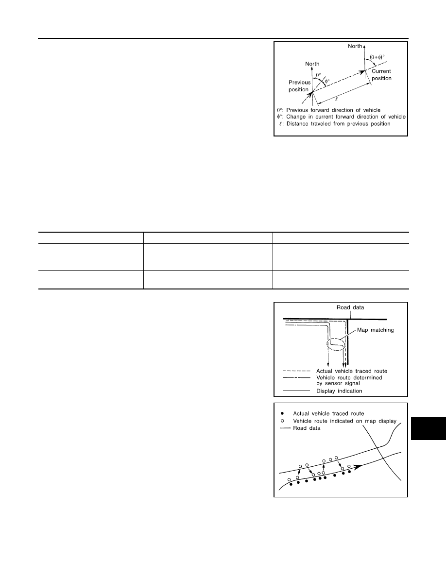
The current vehicle position will be calculated by detecting the dis-

tance the vehicle moved from the previous calculation point and its

direction.

Travel Distance 

Travel distance calculations are based on the vehicle speed input signal. Therefore, the calculation may

become incorrect as the tires wear down. To prevent this, an automatic distance fine adjustment function has

been adopted.

Travel Direction 

Change in the travel direction of the vehicle is calculated by a gyroscope (angular velocity sensor) and a GPS

antenna (GPS information). As the gyroscope and GPS antenna have both merit and demerit, input signals

from them are prioritized in each situation. However, this order of priority may change in accordance with more

detailed travel conditions so that the travel direction is detected more accurately.

Map–Matching

Map–matching is a function that repositions the vehicle on the road

map when a new location is judged to be the most accurate. This is

done by comparing the current vehicle position, calculated by the

method described in the position detection principle, with the road

map data around the vehicle, read from the map data stored on the

HDD.

Therefore, the vehicle position may not be corrected after the vehicle

is driven over a certain distance or time in which GPS information is

hard to receive. In this case, the current-location mark on the display

must be corrected manually.

CAUTION:

The road map data is based on data stored on the HDD.

• In map-matching, alternative routes to reach the destination will be

shown and prioritized, after the road on which the vehicle is cur-

rently driven has been judged and the current-location mark has

been repositioned.

If there is an error in distance and/or direction, the alternative

routes will be shown in different order of priority, and the wrong

road can be avoided.

If two roads are running in parallel, they are of the same priority.

Therefore, the current-location mark may appear on either of them

alternately, depending on maneuvering of the steering wheel and

configuration of the road.

SEL684V

Type

Advantage

Disadvantage

Gyroscope (angular velocity sensor)

• Can detect the vehicle's turning angle quite 

accurately.

• Direction errors may accumulate when the ve-

hicle is driven for long distances without stop-
ping.

GPS antenna (GPS information)

• Can detect the vehicle's travel direction 

(North/South/East/West).

• Correct direction cannot be detected when the 

vehicle speed is low.

SEL685V

SEL686V

AV-400

< SYSTEM DESCRIPTION >

[PREMIUM AUDIO WITH NAVIGATION]

SYSTEM

• Map-matching does not function correctly when the road on which

the vehicle is driving is new and not recorded on the HDD, or when

the road pattern stored in the map data and the actual road pattern

are different due to repair.

When driving on a road not present in the map, the map-matching

function may find another road and position the current-location

mark on it. Then, when the correct road is detected, the current-

location mark may leap to it.

• Effective range for comparing the vehicle position and travel direc-

tion calculated by the distance and direction with the road data

read from the HDD is limited. Therefore, when there is an exces-

sive gap between the current vehicle position and the position on

the map, correction by map-matching is not possible.

GPS (Global Positioning System)

GPS (Global Positioning System) has been developed and con-

trolled by the US Department of Defense. The system utilizes GPS

satellite (NAVSTAR), sending out radio waves while flying on an orbit

around the earth at the height of approx. 21,000 km (13,000 mi).

The GPS receiver calculates the vehicle's position in three dimen-

sions (latitude/longitude/altitude) according to the time lag of the

radio waves received from four or more GPS satellites (three-dimen-

sional positioning). If radio waves were received only from three

GPS satellites, the GPS receiver calculates the vehicle's position in

two dimensions (latitude/longitude), utilizing the altitude data calcu-

lated previously by using radio waves from four or more GPS satel-

lites (two-dimensional positioning).

Accuracy of the GPS will deteriorate under the following conditions.

• In two-dimensional positioning, the GPS accuracy will deteriorate when the altitude of the vehicle position

changes.

• There may be an error of approximately 10 m (30 ft.) in position detected by three-dimensional positioning,

which is more accurate than two-dimensional positioning. The accuracy can be even lower depending on the

arrangement of the GPS satellites utilized for the positioning.

• Position detection is not possible when the vehicle is in an area where radio waves from the GPS satellite do

not reach, such as in a tunnel, parking lot in a building, and under an elevated highway. Radio waves from

the GPS satellites may not be received when some object is located over the GPS antenna.

• Position correction by GPS is not available while the vehicle is stopped.

SPEED SENSITIVE VOLUME SYSTEM

Volume level of this system goes up and down automatically in proportion to the vehicle speed. The control

level can be selected by the customer. Refer to Owner's Manual for operating instructions.

FRONT AUXILIARY INPUT JACKS

• Image and sound can be output from an external device connected to the front auxiliary input jacks.

• AUX image signals are transmitted to each unit as follows:

- To the display unit via AV control unit. 

- To the headrest display units via AV control unit and video distributor.

• AUX sound signals are transmitted to each unit as follows:

- To each speaker via AV control unit and BOSE speaker amp.

- To video distributor via AV control unit.

• Headphone sound signals are transmitted via infrared communication between headrest display units and

headphones.

REAR ENTERTAINMENT SYSTEM

• Image and sound (DVD, USB memory-stored video data and front auxiliary input) played by AV control unit

can be enjoyed in rear seat using headrest display units and headphones.

• Image and sound of an external device connected to rear auxiliary input jacks for rear seat can be enjoyed in

rear seat using headrest display units and headphones. Also, image and sound from rear auxiliary input

jacks can be selected and played individually on each side as well as on both sides.

NOTE:

Image signal and sound signal from rear auxiliary input jacks are not transmitted to front display unit and each

speaker.

ALNIA0671GB

SEL526V

AV

SYSTEM

AV-401

< SYSTEM DESCRIPTION >

[PREMIUM AUDIO WITH NAVIGATION]

C

D

E

F

G

H

I

J

K

L

M

B

A

O

P

Operation Signal

• The rear entertainment system can be controlled by the rear seat remote control.

• The rear seat remote control transmits the operation signal to the remote control receiver built into headrest

display units, which then transmits it to the AV control unit and video distributor.

Headphone Sound

• Sound signals output from AV control unit or rear auxiliary input jacks are transmitted to headrest display

units via video distributor.

• Headphone sound signals are transmitted via infrared communication between headrest display units and

headphones.

Headrest Display Units

• Composite image signals from AV control unit are transmitted to headrest display unit via video distributor.

• Image switch signals from headrest display units are transmitted to AV control unit and video distributor,

according to rear seat remote control operation.

• When image switch signal is transmitted from headrest display unit to AV control unit via AV communication,

image played by AV control unit (DVD, USB memory-stored video data, and front auxiliary input) switches.

• When image switch signal is transmitted from headrest display unit to video distributor, image output from

AV control unit and image output from rear auxiliary input jacks switch.

AROUND VIEW MONITOR SYSTEM

• This system is equipped with wide-angle high-resolution cameras on the front and rear of the vehicle and on

both right and left door mirrors. The images from front view, rear view, front-side view (RH side), and birds-

eye view that shows the view from the top of the vehicle are displayed to monitor the vehicle surroundings. 

• Around view monitor control unit cuts out and expands the image received from each camera to create each

view. 

• The sonar indicator is viewed on display (superimposed on the camera image) in combination with the cam-

era assistance sonar system to warn of the approach of an obstacle. 

• In front view and rear view, the vehicle width, distance lines and predictive course lines are superimposed

and displayed. In front-side view, the vehicle distance guiding line and vehicle width guiding line are dis-

played. 

• The Birds-Eye view converts the images from 4 cameras into the overhead view and displays the status of

the vehicle. The vehicle icon and sonar indicator on the Birds-Eye view display are rendered by around view

monitor control unit. 

Around View Monitor Screen

• Around view monitor combines and displays the travel direction view and Birds-Eye view, Front-Side view

and then displays the sonar indicator on the Birds-Eye view, Front-Side view, Rear wide view.

• AV control unit renders the Change View switch, view icon, warning message on display. 

Operation Description

NOTE:

The first, second, and third camera image displayed when switched to the camera image display depends on

the settings of Camera View Priority.

• Around view monitor operates by pressing the CAMERA switch on the A/C and AV switch assembly and

shifting the selector lever to the R position. 

• When the selector lever is in any position other than R, the screen is switched to the around view monitor by

pressing the CAMERA switch.

• The screen is switched to the around view monitor by shifting the selector lever to the R position. 

• The around view monitor’s, Birds-Eye view, Front-side view or rear wide view (rear only) can be switched by

pressing the CAMERA switch. 

• The around view monitor is cancelled 3 minutes after pressing the CAMERA switch, and the display returns

to the previous screen.

• ON/OFF setting of sonar indicator display on the Front-Side view screen can be performed. 

• In Birds-Eye view, the invisible area is displayed on the image to specify the boundary of the 4 cameras. The

invisible area is displayed in yellow in the Birds-Eye view after turning the ignition switch ON. 

• The sonar operates only when the camera screen is displayed. 

VEHICLE INFORMATION FUNCTION

• Status of audio, climate control system, fuel economy, maintenance and navigation are displayed.

• AV control unit displays the fuel consumption status while receiving data signal through CAN communication

from ECM and combination meter.

• AV control unit is connected to BCM via CAN communication transmitting/receiving for the vehicle settings

function.

AV-402

< SYSTEM DESCRIPTION >

[PREMIUM AUDIO WITH NAVIGATION]

SYSTEM

INTELLIGENT KEY INTERLOCKING FUNCTION

The AV control unit recognizes a door-unlocked state of Intelligent Key according to an Intelligent Key recogni-

tion signal transmitted from BCM and saves two different types of audio settings and navigation settings.

Settings saved in the AV control unit

• Map display

• Route guidance

• Locator

• Route search

• Sound quality

• Radio preset

• Language


Content   ..  141  142  143  144   ..