Nissan Pathfinder. Manual - part 1198


  Index      Nissan     Nissan Pathfinder (2014 year) - Service and Repair Manual


Search            


Content   ..  1196  1197  1198  1199   ..


Nissan Pathfinder. Manual - part 1198


WCS

DIAGNOSIS SYSTEM (COMBINATION METER)

WCS-9

< SYSTEM DESCRIPTION >

C

D

E

F

G

H

I

J

K

L

M

B

A

O

P

DIAGNOSIS SYSTEM (COMBINATION METER)

Description

INFOID:0000000009730851

COMBINATION METER SELF-DIAGNOSIS MODE

The following meter functions can be checked during Combination Meter Self-Diagnosis Mode:

• Pointer sweep of speedometer, tachometer and gauges.

• Illumination of all LCD segments and color patterns for meter displays.

• Illumination of all lamps/LEDs that are controlled by the combination meter (regardless of switch status).

STARTING COMBINATION METER SELF-DIAGNOSIS MODE

NOTE:

• Check combination meter power supply and ground circuits if self-diagnosis mode does not start. Refer to

WCS-27, "COMBINATION METER : Diagnosis Procedure"

. Replace combination meter if power supply and

ground circuits are found to be normal and self-diagnosis mode does not start. Refer to 

MWI-82, "Removal

and Installation"

.

• Combination meter self-diagnosis mode will function with the ignition switch in ON. Combination meter self-

diagnosis mode will exit upon turning the ignition switch to OFF. 

How to Initiate Self-Diagnosis Mode

1. Press and hold the trip reset switch while turning the ignition switch ON. After 2 seconds release trip reset

switch, then press the trip reset switch 3 times within 7 seconds after the ignition switch is turned ON.

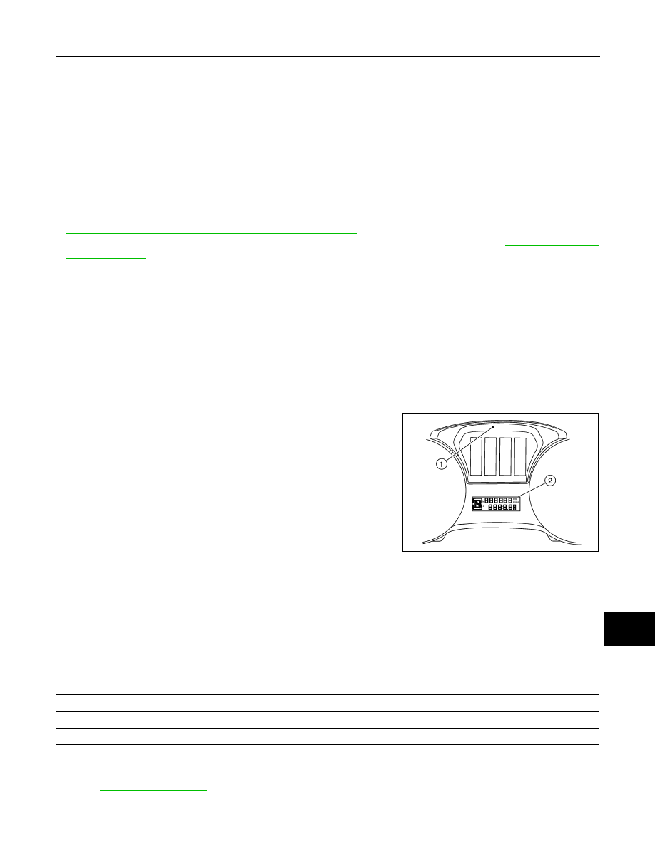
2. When the diagnosis function is activated, the meter illuminates all of the following:

• Warning lights/indicators.

• Meter assembly.

• Information display color bars red, green, blue and white (1).

• Odometer, trip A/B odometers and CVT indicator  LCD display segments (2).

3.    Pressing and holding the trip reset switch performs the pointer sweep test.

CONSULT Function (METER/M&A)

INFOID:0000000009730852

CAUTION:

After disconnecting the CONSULT vehicle interface (VI) from the data link connector, the ignition must

be cycled OFF 

 ON (for at least 5 seconds)  OFF.  If this step is not performed, the BCM may not go

to "sleep mode", potentially causing a discharged battery and a no-start condition.

APPLICATION ITEMS

CONSULT can display each diagnostic item using the diagnostic test modes shown.

SELF DIAG RESULT

Refer to 

MWI-29, "DTC Index"

.

DATA MONITOR

AWNIA2543GB

METER/M&A Diagnosis mode

Description

Self Diagnostic Result

Displays combination meter self-diagnosis results.

Data Monitor

Displays combination meter input/output data in real time.

Warning History

Lighting history of the warning lamp and indicator lamp can be checked.

WCS-10

< SYSTEM DESCRIPTION >

DIAGNOSIS SYSTEM (COMBINATION METER)

Display Item List

X: Applicable

Display item [Unit]

MAIN

SIGNALS

Description

SPEED METER
[mph or km/h]

X

Displays the value of vehicle speed signal.

SPEED OUTPUT
[mph or km/h]

X

Vehicle speed signal value transmitted to other units via CAN communication.

ODO OUTPUT
[mi or km]

Odometer signal value transmitted to other units via CAN communication.

TACHO METER
[rpm]

X

Value of the engine speed signal received from ECM via CAN communication.

FUEL METER
[L]

X

Fuel level indicated on combination meter.

W TEMP METER
[

°F] or [°C]

X

Displays the value of engine coolant temperature signal, which is input from ECM.

ABS W/L
[On/Off]

Displays [ON/OFF] condition of ABS warning indicator. 

VDC/TCS IND
[On/Off]

Displays [ON/OFF] condition of VDC OFF warning lamp.  

SLIP IND
[On/Off]

Displays [ON/OFF] condition of SLIP indicator lamp.

BRAKE W/L
[On/Off]

Displays [ON/OFF] condition of  brake warning indicator.

DOOR W/L
[ON/OFF]

Displays [ON/OFF] condition of door open or liftgate open warning message.

HI-BEAM IND
[ON/OFF]

Displays [ON/OFF] condition of high beam indicator.

TURN IND
[On/Off]

Displays [ON/OFF] condition of turn indicator.

FR FOG IND
[On/Off]

Displays [ON/OFF] condition of front fog lamp indicator.

LIGHT IND
[On/Off]

Displays [ON/OFF] condition of light indicator.

OIL W/L
[ON/OFF]

Displays [ON/OFF] condition of low oil pressure warning message.

MIL
[ON/OFF] 

Displays [ON/OFF] condition of malfunction indicator.

CRUISE IND
[Off]

Displays [ON/OFF] condition of CRUISE indicator in the information display.

SET IND
[On/Off]

Displays [ON/OFF] condition of SET indicator in the information display.

O/D OFF IND
[On/Off]

Displays [ON/OFF] condition of O/D OFF indicator.

CVT IND
[On/Off]

Displays [ON/OFF] condition of CVT indicator in the information display.

4WD W/L
[On/Off]

Displays [ON/OFF] condition of 4WD warning message in the information display.

FUEL W/L
[On/Off]

Displays [ON/OFF] condition of low-fuel warning message.

WASHER W/L
[On/Off]

Displays [ON/OFF] condition of low washer fluid warning message.

KEY G/Y W/L
[On/Off]

Displays [ON/OFF] condition of key green warning lamp.

WCS

DIAGNOSIS SYSTEM (COMBINATION METER)

WCS-11

< SYSTEM DESCRIPTION >

C

D

E

F

G

H

I

J

K

L

M

B

A

O

P

EPS W/L
[On/Off]

Displays [ON/OFF] condition of EPS warning indicator.

LCD
[B&P/Off]

Displays [B&P/OFF] condition of the shift selector button.

SHIFT IND
[P,N,D,L]

Displays [P,N,D,L] shift selector position.

4WD IND
[AUTO, LOCK, 2W]

Displays [ON/OFF] condition of 4WD modes in the information display.

TOW MODE IND
[On/Off]

Displays [ON/OFF] condition of tow mode indicator.

FUEL CAP W/L
[On/Off]

Displays [ON/OFF] condition of loose fuel cap warning message.

O/D OFF SW
[On/Off]

Displays [ON/OFF] condition of O/D OFF switch.

COMP F/B SIG
[On/Off]

A/C compressor activation condition that ECM judges according to the water tem-
perature and the acceleration degree.

PKB SW
[On/Off]

Displays [ON/OFF] condition of parking brake switch.

BRAKE OIL SW
[On/Off]

Displays [ON/OFF] condition of brake fluid level switch.

BUCKLE SW
[On/Off]

Displays [ON/OFF] condition of seat belt buckle switch (driver seat).

PASS BUCKLE SW
[On/Off]

Displays [ON/OFF] condition of seat belt buckle switch (passenger seat).

TOW MODE SW
[On/Off]

Displays [ON/OFF] condition of tow mode switch.

DISTANCE
[mi] or [km]

Displays distance to empty.

OUTSIDE TEMP
[

°F or °C]

Displays the ambient temperature which is input from ambient sensor.

FUEL LOW SIG
[On/Off]

Displays the [ON/OFF] condition the fuel level low warning signal. 

BUZZER
[On/Off]

X

Buzzer status (in the combination meter) is detected from the buzzer output signal 
received from each unit via CAN communication and the warning output condition 
of the combination meter.

BATTERY CIRCUIT STATUS
 [NORMAL/OPEN]

Displays [NORMAL/OPEN] condition of battery circuit status.

PARKING AIDS DSP
[On/Off]

Displays [On/Off] condition of parking aids display setting.

PARKING AIDS SENSOR
[On/Off]

Displays [On/Off] condition of parking aids sensor setting.

PARKING AIDS VOLUME
[Low/Medium/High]

Displays [Low/Medium/High] condition of parking aids volume.

PARKING AIDS RANGE
[Near/Medium/Far]

Displays [Near/Medium/Far] condition of parking aids range.

TPMS DISP 
[ON/OFF]

Displays [ON/OFF] condition of TPMS display.

TIRE STATUS FR
[ON/OFF]

Displays [ON/OFF] condition of tire status.

TIRE STATUS FL
[ON/OFF]

Displays [ON/OFF] condition of tire status.

Display item [Unit]

MAIN

SIGNALS

Description

WCS-12

< SYSTEM DESCRIPTION >

DIAGNOSIS SYSTEM (COMBINATION METER)

TIRE STATUS RR
[ON/OFF]

Displays [ON/OFF] condition of tire status.

TIRE STATUS RL
[ON/OFF]

Displays [ON/OFF] condition of tire status.

SONER SET AVA
[Available/Unavailable]

Displays [AVAILABLE/UNAVAILABLE] condition of meter setting.

STRG SW INPUT
[SW1,SW2,SW3,SW4,SW5,SW6,S
W7,SW8,SW9,SW10]

Displays [SW1,SW2,SW3,SW4,SW5,SW6,SW7,SW8,SW9,SW10] condition of  
steering switch.

ITS SONER SET OUTPUT

Displays status of sonar.

SONAR DET STA
[ON/OFF]

Displays [ON/OFF] condition of sonar detection area.

SONAR WARN
[OFF/SENSOR DEACTIVE/SEN-
SOR ERROR]

Displays [OFF/SENSOR DEACTIVE/SENSOR ERROR] condition of sonar warn-
ing.

SONAR DET DSP RC
[ON/OFF]

Displays [ON/OFF] condition of RC sonar detection display.

SONAR DSP AREA RC
[ON/OFF]

Displays [ON/OFF] condition of RC sonar detection area image.

SONAR DET DSP RL
[ON/OFF]

Displays [ON/OFF] condition of RL sonar detection display.

SONAR DSP AREA RL
[ON/OFF]

Displays [ON/OFF] condition of RL sonar detection area image.

SONAR DET DSP RR
[ON/OFF]

Displays [ON/OFF] condition of RR sonar detection display.

SONAR DSP AREA RR
[ON/OFF]

Displays [ON/OFF] condition of RR sonar detection area image.

SONAR DET DSP FC
[ON/OFF]

Displays [ON/OFF] condition of  FC sonar detection area.

SONAR DSP AREA FC
[ON/OFF]

Displays [ON/OFF] condition of  FC sonar detection area image.

SONAR DET DSP FL
[ON/OFF]

Displays [ON/OFF] condition of FL sonar detection display.

SONAR DSP AREA FL
[ON/OFF]

Displays [ON/OFF] condition of FL sonar detection area image.

SONAR DET DSP FR
[ON/OFF]

Displays [ON/OFF] condition of FR sonar detection display.

SONAR DSP AREA FR
[ON/OFF]

Displays [ON/OFF] condition of FR sonar detection area image.

SONAR DIST DSP
[ON/OFF]

Displays sonar distance status.

TPMS PRESS L 
[ON/OFF]

Displays [ON/OFF] condition of low tire pressure message in the information dis-
play.

TPMS MALF 
[ON/OFF]

Displays [ON/OFF] condition of TPMS warning indicator.

4WD CL TMP H
[ON/OFF]

Displays [ON/OFF] condition of 4WD clutch high temperature message in the in-
formation display.

4WD TIRE CHCK
[ON/OFF]

Displays [ON/OFF] condition of 4WD tire check message in the information dis-
play.

4WD SYS MALF
[ON/OFF]

Displays [ON/OFF] condition of 4WD system malfunction message in the informa-
tion display.

Display item [Unit]

MAIN

SIGNALS

Description


Content   ..  1196  1197  1198  1199   ..