Content .. 1184 1185 1186 1187 ..
Nissan Pathfinder. Manual - part 1186
OUTPUT SPEED SENSOR
TM-203
< REMOVAL AND INSTALLATION >
[CVT: RE0F10E]
C
E
F
G
H
I
J
K
L
M
A
B
TM
N
O
P
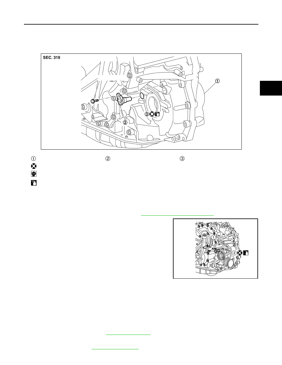
OUTPUT SPEED SENSOR
Exploded View
INFOID:0000000009177666
Removal and Installation
INFOID:0000000009177667
REMOVAL
1. Disconnect the battery negative terminal. Refer to
PG-90, "Removal and Installation"
2. Disconnect the harness connector from output speed sensor (1).
3. Remove the output speed sensor bolt, then the output speed
sensor (1).
4. Remove the O-ring (2) from the output speed sensor (1).
CAUTION:
Do not reuse O-ring.
INSTALLATION
Installation is in the reverse order of removal.
CAUTION:
• Do not reuse O-ring.
• Apply Genuine NISSAN CVT Fluid NS-3 to the O-ring.
Inspection and Adjustment
INFOID:0000000009177668
INSPECTION AFTER INSTALLATION
Check for CVT fluid leakage. Refer to
.
ADJUSTMENT AFTER INSTALLATION
Adjust CVT fluid level. Refer to
Transaxle assembly
Output speed sensor
O-ring
: Always replace after every disassembly.
: N·m (kg-m, in-lb)
: Apply CVT fluid
JSDIA3727GB
ALDIA0363ZZ