Nissan Pathfinder. Manual - part 1139


  Index      Nissan     Nissan Pathfinder (2014 year) - Service and Repair Manual


Search            


Content   ..  1137  1138  1139  1140   ..


Nissan Pathfinder. Manual - part 1139


COMPONENT PARTS

TM-15

< SYSTEM DESCRIPTION >

[CVT: RE0F10E]

C

E

F

G

H

I

J

K

L

M

A

B

TM

N

O

P

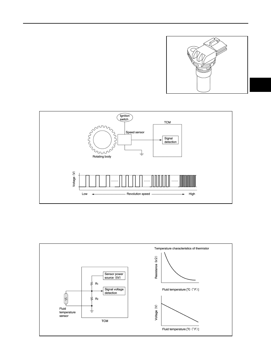
CVT CONTROL SYSTEM : Output Speed Sensor

INFOID:0000000009177482

• The output speed sensor is installed to the back side of transaxle

case.

• The output speed sensor detects final gear speed.

• The output speed sensor generates an ON-OFF pulse signal according to the rotating body speed. TCM

judges the rotating body speed from the pulse signal.

CVT CONTROL SYSTEM : CVT Fluid Temperature Sensor

INFOID:0000000009177483

• The CVT fluid temperature sensor is installed to control valve.

• The CVT fluid temperature sensor detects CVT fluid temperature in oil pan.

• The fluid temperature sensor uses a thermistor, and changes the signal voltage by converting changes in the

CVT fluid temperature to a resistance value. TCM evaluates the CVT fluid temperature from the signal volt-

age value. 

JSDIA3073ZZ

JSDIA1824GB

JSDIA1825GB

TM-16

< SYSTEM DESCRIPTION >

[CVT: RE0F10E]

COMPONENT PARTS

CVT CONTROL SYSTEM : Primary Pressure Sensor

INFOID:0000000009177484

• The primary pressure sensor is installed to control valve.

• The primary pressure sensor detects the pressure applied to the primary pulley. 

• When pressure is applied to the ceramic device in the primary pressure sensor, the ceramic device is

deformed, resulting in voltage change. TCM evaluates the primary pressure from its voltage change. Voltage

is increased along with pressure increase. 

CVT CONTROL SYSTEM : Secondary Pressure Sensor

INFOID:0000000009177485

• The secondary pressure sensor is installed to control valve.

• The secondary pressure sensor detects the pressure applied to the secondary pulley. 

• When pressure is applied to the metal diaphragm in the secondary pressure sensor, the metal diaphragm is

deformed, resulting in voltage change. TCM evaluates the secondary pressure from its voltage change. Volt-

age is increased along with pressure increase.

CVT CONTROL SYSTEM : Line Pressure Solenoid Valve

INFOID:0000000009177486

• The line pressure solenoid valve is installed to control valve.

• The line pressure solenoid valve controls the pressure regulator valve. For information about the pressure

regulator valve, refer to 

TM-25, "TRANSAXLE : Component Description"

.

JSDIA1831GB

JSDIA1831GB

COMPONENT PARTS

TM-17

< SYSTEM DESCRIPTION >

[CVT: RE0F10E]

C

E

F

G

H

I

J

K

L

M

A

B

TM

N

O

P

• The line pressure solenoid valve uses the linear solenoid valve [N/

H (normal high) type].

NOTE:

• The principle of the linear solenoid valve utilizes the fact that the

force pressing on the valve spool installed inside the coil

increases nearly in proportion to the current. This allows it to pro-

duce a fluid pressure that is proportional to this pressing force.

• The N/H (normal high) produces hydraulic control when the coil

is not energized.

CVT CONTROL SYSTEM : Primary Pressure Solenoid Valve

INFOID:0000000009177487

• The primary pressure solenoid valve is installed to control valve.

• The primary pressure solenoid valve controls the primary reducing valve. For information about the primary

reducing valve, refer to 

TM-25, "TRANSAXLE : Component Description"

.

• The primary pressure solenoid valve uses the linear solenoid valve

[N/H (normal high) type].

NOTE:

• The principle of the linear solenoid valve utilizes the fact that the

force pressing on the valve spool installed inside the coil

increases nearly in proportion to the current. This allows it to pro-

duce a fluid pressure that is proportional to this pressing force.

• The N/H (normal high) produces hydraulic control when the coil

is not energized.

CVT CONTROL SYSTEM : Secondary Pressure Solenoid Valve

INFOID:0000000009177488

• The secondary pressure solenoid valve is installed to control valve.

• The secondary pressure solenoid valve controls the secondary reducing valve. For information about the

secondary reducing valve, refer to 

TM-25, "TRANSAXLE : Component Description"

.

• The secondary pressure solenoid valve uses the linear solenoid

valve [N/H (normal high) type].

NOTE:

• The principle of the linear solenoid valve utilizes the fact that the

force pressing on the valve spool installed inside the coil

increases nearly in proportion to the current. This allows it to pro-

duce a fluid pressure that is proportional to this pressing force.

• The N/H (normal high) produces hydraulic control when the coil

is not energized.

CVT CONTROL SYSTEM : Torque Converter Clutch Solenoid Valve

INFOID:0000000009177489

• The torque converter clutch solenoid valve is installed to control valve.

• The torque converter clutch solenoid valve controls the torque converter clutch control valve. For information

about the torque converter clutch control valve, refer to 

TM-25, "TRANSAXLE : Component Description"

.

JSDIA3647GB

JSDIA3647GB

JSDIA3647GB

TM-18

< SYSTEM DESCRIPTION >

[CVT: RE0F10E]

COMPONENT PARTS

• The torque converter clutch solenoid valve utilizes a linear sole-

noid valve [N/L (normal low) type].

NOTE:

• The principle of the linear solenoid valve utilizes the fact that the

force pressing on the valve spool installed inside the coil

increases nearly in proportion to the current. This allows it to pro-

duce a fluid pressure that is proportional to this pressing force.

• The N/L (normal low) type does not produce hydraulic control

when the coil is not energized.

CVT CONTROL SYSTEM : Select Solenoid Valve

INFOID:0000000009177490

• The select solenoid valve is installed to control valve.

• The select solenoid valve adjusts the forward clutch engaging pressure and the reverse brake engaging

pressure. 

• The select solenoid valve uses the linear solenoid valve [N/H (nor-

mal high) type].

NOTE:

• The principle of the linear solenoid valve utilizes the fact that the

force pressing on the valve spool installed inside the coil

increases nearly in proportion to the current. This allows it to pro-

duce a fluid pressure that is proportional to this pressing force.

• The N/H (normal high) produces hydraulic control when the coil

is not energized.

CVT CONTROL SYSTEM : Overdrive Control Switch

INFOID:0000000009177491

• The overdrive control switch is installed to the selector lever handle. 

• When the OD OFF indicator lamp on the combination meter is OFF and the overdrive control switch is

pressed, the overdrive is cancelled and the OD OFF indicator lamp is ON.

• When the OD OFF indicator lamp on the combination meter is ON and the overdrive control switch is

pressed, the overdrive is active and the OD OFF indicator lamp is OFF. 

CVT CONTROL SYSTEM : Tow Mode Switch

INFOID:0000000009177492

• The Tow mode switch is installed to instrument lower panel (LH). 

• When the Tow mode indicator lamp on the combination meter is OFF and the Tow mode switch is pressed,

the Tow mode is active and the Tow mode indicator lamp is ON.

• When the Tow mode indicator lamp on the combination meter is ON and the Tow mode switch is pressed,

the Tow mode is cancelled and the Tow mode indicator lamp is OFF. 

CVT CONTROL SYSTEM : OD OFF Indicator Lamp

INFOID:0000000009177493

• OD OFF indicator lamp is positioned on the combination meter. 

• OD OFF indicator lamp is ON when set to the overdrive OFF. 

• OD OFF indicator lamp turns on for a certain period of time when

the ignition switch turns ON, and then turns OFF.

JSDIA3648GB

JSDIA3647GB

Condition (status)

OD OFF indicator lamp

Ignition switch OFF.

OFF

Ignition switch ON.

ON (Approx. 2 sec.)

Overdrive control switch is pressed 
when the selector lever is in the “D” po-
sition and the OD OFF indicator lamp is 
OFF 

ON

JPNIA1891ZZ


Content   ..  1137  1138  1139  1140   ..