Nissan Pathfinder. Manual - part 1110


  Index      Nissan     Nissan Pathfinder (2014 year) - Service and Repair Manual


Search            


Content   ..  1108  1109  1110  1111   ..


Nissan Pathfinder. Manual - part 1110


STEERING WHEEL

ST-19

< BASIC INSPECTION >

C

D

E

F

H

I

J

K

L

M

A

B

ST

N

O

P

STEERING WHEEL

Inspection

INFOID:0000000009177070

CONDITION OF INSTALLATION

• Check installation condition of power steering gear, front suspension, front drive shaft and steering column.

• Check if movement exists when steering wheel is moved up and down, to the left and right and to the axial

direction.

• Verify that the power steering gear nuts are tightened to specification. Refer to 

ST-48, "Exploded View"

.

STEERING WHEEL PLAY

1. Turn tires straight ahead, start engine, then turn steering wheel to the left and right lightly. Measure steer-

ing wheel movement on the outer circumference of the steering wheel when it is turned to the point where

tires start moving.

NEUTRAL POSITION ON STEERING WHEEL

• Check neutral position on steering wheel after confirming that front wheel alignment is correct. Refer to 

FSU-

5, "Inspection and Adjustment"

.

1. Turn tires straight ahead, check if steering wheel is in the neutral position.
2. If it is not in the neutral position, remove steering wheel and reinstall it correctly.
3. If the neutral position cannot be attained by repositioning the steering wheel two teeth or less on steering

stem, loosen tie-rod lock nuts of power steering gear outer sockets, then adjust tie-rods by the same

amount in the opposite direction.

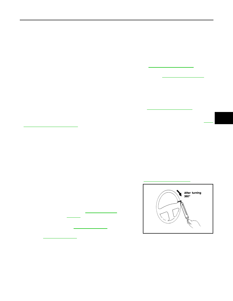
STEERING WHEEL TURNING FORCE

1. Park vehicle on a level, dry surface and set parking brake.
2. Start engine.
3. Bring power steering fluid up to operating temperature.
4. Verify that the tires are inflated to the specified pressure. Refer to 

WT-65, "Tire Air Pressure"

.

5. Check steering wheel turning force using Tool when steering

wheel has been turned 360

° from the neutral position.

6. If steering wheel turning force is out of specification, inspect

steering column. Refer to 

ST-21, "Inspection"

.

7. If steering column meets specification, inspect steering gear.

Refer to 

ST-23, "Inspection"

.

CHECKING FRONT WHEEL TURNING ANGLE 

Steering wheel axial end play

: Refer to 

ST-60, "Steering Wheel"

.

Steering wheel play 

: Refer to 

ST-60, "Steering Wheel"

.

Tool number

: ( — ) (J-44372)

Steering wheel 
turning force

: Refer to 

ST-60, "Steering 

Wheel"

.

WGIA0035E

ST-20

< BASIC INSPECTION >

STEERING WHEEL

• Check front wheel turning angle after toe-in inspection. Place front

wheels on turning radius gauges and rear wheels on stands.

Check the maximum inner and outer wheel turning angles for LH

and RH road wheels.

• Measure the turning angles with the engine at idle, then turn the

steering wheel from full left stop to full right stop and measure the

turning angle. Refer to 

ST-60, "Steering Angle"

.

• Measure the rack stroke specification with vehicle in neutral posi-

tion. Refer to 

ST-61, "Power Steering Gear"

.

FAA0016D

Inner wheel angle (A)

: Refer to

ST-60, "Steering 

Angle"

.

Outer wheel angle (B)

: Refer to 

ST-60, "Steering 

Angle"

.

SGIA0055E

Rack stroke in neutral 
position (L)

: Refer to 

ST-61, "Power 

Steering Gear"

.

AWGIA0003GB

STEERING COLUMN

ST-21

< BASIC INSPECTION >

C

D

E

F

H

I

J

K

L

M

A

B

ST

N

O

P

STEERING COLUMN

Inspection

INFOID:0000000009177071

HOLE COVER SEAL, HOLE COVER AND LOWER SHAFT

Check each part of hole cover seal, hole cover and steering column and lower shaft for damage or other mal-

functions. Replace if necessary.

STEERING COLUMN

• Check each part of steering column for damage or other malfunctions. Replace entire steering column if any

parts are damaged.

• Measure the length (L) as shown if vehicle has been involved in a

minor collision. Replace steering column if outside the specifica-

tions.

• Measure steering column rotating torque using Tool. Replace steering column if outside the standard.

• Check tilt and telescopic mechanism operating range (L

1

), (L

2

) as

shown.

Steering column length (L)

: Refer to

ST-60, "Steering 

Column"

.

ALGIA0105ZZ

Tool number

: ST3127S000 (J-25765-A)

Rotating torque

: Refer to 

ST-60, "Steering Column"

.

Tilt operating range (L

1

)

: Refer to 

ST-60, "Steering 

Column"

.

Telescopic operating range 
(L

2

)

: Refer to

ST-60, "Steering 

Column"

.

ALGIA0106ZZ

ST-22

< BASIC INSPECTION >

POWER STEERING OIL PUMP

POWER STEERING OIL PUMP

Inspection

INFOID:0000000009177072

RELIEF OIL PRESSURE

1. Connect the Tool between oil pump discharge connector and

high-pressure hose. Bleed air from the hydraulic circuit while

opening valve fully. Refer to 

ST-42, "Air Bleeding Hydraulic Sys-

tem"

.

2. Start engine. Run engine until power steering fluid temperature

reaches 50

° - 80°C (122° - 176°F).

CAUTION:

• Leave the valve of the hydraulic pressure gauge fully

open while starting and running engine. If engine is

started with the valve closed, the hydraulic pressure in oil

pump goes up to the relief pressure along with unusual

increase of fluid temperature.

• Be sure to keep hose clear of belts and other parts when

engine is started.

3. Fully close the Tool valve with engine at idle and measure the

relief oil pressure.

CAUTION:

Do not keep valve closed for 10 seconds or longer.

4. Open the valve slowly after measuring. Replace oil pump if the relief oil pressure is outside the standard.
5. After inspection, disconnect the Tool from hydraulic circuit, then add fluid and bleed air. Refer to 

ST-42,

"Air Bleeding Hydraulic System"

.

Tool numbers

: KV48103500 (J-26357) 
: KV48102500 (J-33914)

Relief oil pressure : Refer to 

ST-62, "Power Steering 

Oil Pump"

SGIA0915E


Content   ..  1108  1109  1110  1111   ..