Nissan Pathfinder. Manual - part 101


  Index      Nissan     Nissan Pathfinder (2014 year) - Service and Repair Manual


Search            


Content   ..  99  100  101  102   ..


Nissan Pathfinder. Manual - part 101


AV

AV CONTROL UNIT

AV-231

< ECU DIAGNOSIS INFORMATION >

[MID AUDIO WITH BOSE]

C

D

E

F

G

H

I

J

K

L

M

B

A

O

P

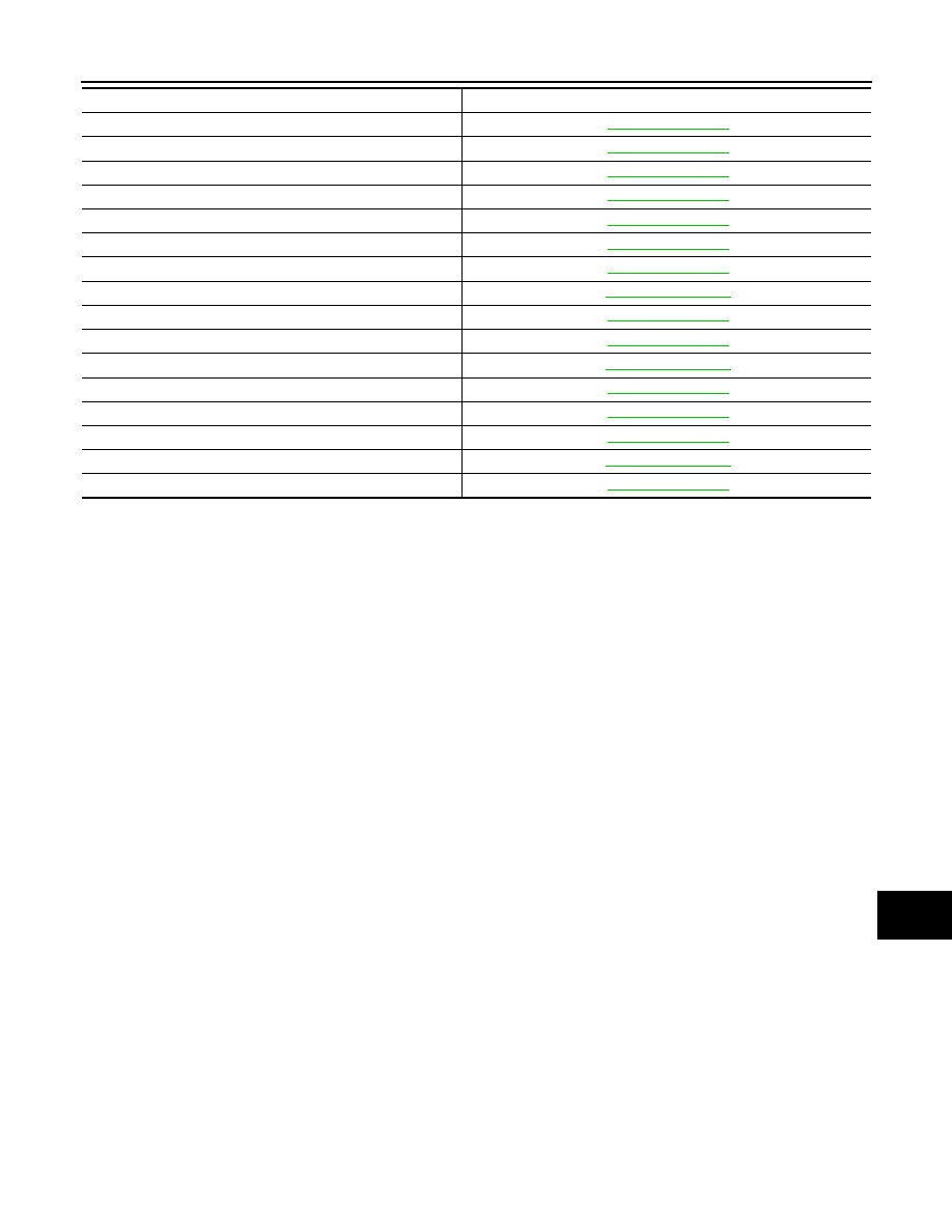
U1225: USB CONTROLLER

AV-289, "DTC Logic"

U1227: DVD COMM

AV-290, "DTC Logic"

U1228: SUB CPU CONN

AV-291, "DTC Logic"

U1229: iPod CERTIFICATION

AV-292, "DTC Logic"

U122A: CONFIG UNFINISH

AV-293, "DTC Logic"

U122E: Built-in AUDIO CONN

AV-294, "DTC Logic"

U1231: AMP TEMP

AV-295, "DTC Logic"

U1240: SWITCH CONN

AV-303, "Description"

U1243: FRONT DISP CONN

AV-296, "DTC Logic"

U1255: SAT CONN

AV-298, "DTC Logic"

U1256: HAND FREE CONN

AV-303, "Description"

U1263: USB OVERCURRENT

AV-530, "DTC Logic"

U1264: ANTENNA AMP TERMINAL

AV-531, "DTC Logic"

U1265: AMP ON TERMINAL

AV-302, "DTC Logic"

U1300: AV COMM CIRCUIT

AV-303, "Description"

U1310: CONTROL UNIT

AV-304, "DTC Logic"

CONSULT Display

Reference Page

AV-232

< ECU DIAGNOSIS INFORMATION >

[MID AUDIO WITH BOSE]

DISPLAY UNIT

DISPLAY UNIT

Reference Value

INFOID:0000000009174539

TERMINAL LAYOUT

PHYSICAL VALUES

AWNIA1727ZZ

Terminal

(Wire color)

Description

Condition

Reference value

(Approx.)

+

Signal name

Input/

Output

1

(B)

Ground Ground

Ignition 

switch 

ON 

0V

2

(L)

Ground Inverter VCC

Input

Ignition 

switch 

ACC

9V

3

(V)

Ground Signal VCC

Input

Ignition 

switch 

ACC

9V

4

(W)

Ground Composite image ground

Ignition 

switch 

ON 

0V

5

Shield

6

(B)

Ground RGB signal (G: green)

Input

Ignition 

switch 

ON

Start Confirmation/Adjust-
ment mode, and then dis-
play color bar by selecting 
“Color Spectrum Bar” on 
Display Diagnosis screen.

7

Shield

8

(G)

Ground

Horizontal synchronizing 
(HP) signal

Output

Ignition 

switch 

ON

JSNIA1030ZZ

SKIB3601E

AV

DISPLAY UNIT

AV-233

< ECU DIAGNOSIS INFORMATION >

[MID AUDIO WITH BOSE]

C

D

E

F

G

H

I

J

K

L

M

B

A

O

P

9

(W)

Ground RGB area (YS) signal

Input

Ignition 

switch 

ON

At RGB image is displayed.

5V

At DVD image is displayed.

11

(W)

Ground

Communication signal
(CONT

→DISP)

Input

Ignition 

switch 

ON

When adjusting display 
brightness.

13

(LG)

Ground Inverter ground

Ignition 

switch 

ON

0V

14

(B)

Ground Signal ground

Ignition 

switch 

ON

0V

15

(B)

Ground Composite image signal

Input

Ignition 

switch 

ON

At rear view camera image 
is displayed.

17

(R)

Ground RGB signal (R: red)

Input

Ignition 

switch 

ON

Start Confirmation/Adjust-
ment mode, and then dis-
play color bar by selecting 
“Color Spectrum Bar” on 
Display Diagnosis screen.

18

(W)

Ground RGB signal (B: blue)

Input

Ignition 

switch 

ON

Start Confirmation/Adjust-
ment mode, and then dis-
play color bar by selecting 
“Color Spectrum Bar” on 
Display Diagnosis screen.

Terminal

(Wire color)

Description

Condition

Reference value

(Approx.)

+

Signal name

Input/

Output

PKIB4948J

PKIB5039J

SKIB2251J

JSNIA1029ZZ

JSNIA1031ZZ

AV-234

< ECU DIAGNOSIS INFORMATION >

[MID AUDIO WITH BOSE]

DISPLAY UNIT

19

(B)

Ground RGB synchronizing signal

Input

Ignition 

switch 

ON

20

(R)

Ground

Vertical synchronizing (VP) 
signal

Output

Ignition 

switch 

On

21

Shield

22

(B)

Ground

Communication signal
(DISP

→CONT)

Output

Ignition 

switch 

ON

When adjusting display 
brightness.

23

Shield

Terminal

(Wire color)

Description

Condition

Reference value

(Approx.)

+

Signal name

Input/

Output

SKIB3603E

SKIB3598E

PKIB5039J


Content   ..  99  100  101  102   ..