Nissan Pathfinder. Manual - part 29


  Index      Nissan     Nissan Pathfinder (2014 year) - Service and Repair Manual


Search            


Content   ..  27  28  29  30   ..


Nissan Pathfinder. Manual - part 29


ADP-108

< DTC/CIRCUIT DIAGNOSIS >

SEAT MEMORY SWITCH

4. Check continuity between driver seat control unit harness connector and ground.

Is the inspection result normal?

YES

>> Replace driver seat control unit. Refer to 

ADP-161, "Removal and Installation"

.

NO

>> Repair or replace harness.

3.

 CHECK MEMORY SWITCH GROUND CIRCUIT

Check continuity between seat memory switch harness connector and ground.

Is the inspection result normal?

YES

>> GO TO 4.

NO

>> Repair or replace harness.

4.

 CHECK SEAT MEMORY SWITCH

Refer to 

ADP-108, "Component Inspection"

.

Is the inspection result normal?

YES

>> Check intermittent incident. Refer to 

GI-49, "Intermittent Incident"

.

NO

>> Replace seat memory switch. Refer to 

ADP-163, "Removal and Installation"

.

Component Inspection

INFOID:0000000009176609

1.

 CHECK SEAT MEMORY SWITCH

1. Turn ignition switch OFF.

2. Disconnect seat memory switch.

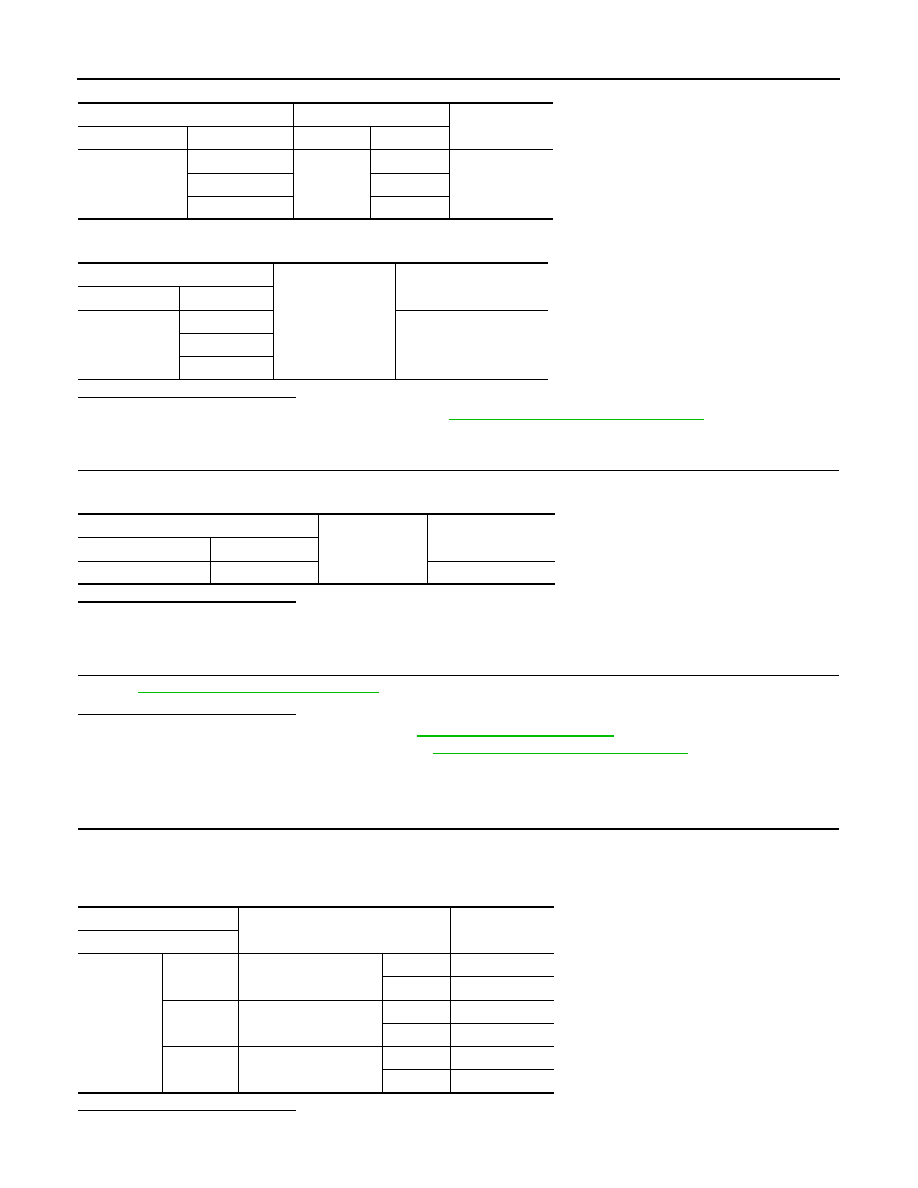
3. Check continuity between seat memory switch terminals.

Is the inspection result normal?

YES

>> Inspection End.

Driver seat control unit

Seat memory switch

Continuity

Connector

Terminal

Connector

Terminal

B209

11

D60

16

Yes

21

2

27

10

Driver seat control unit

Ground

Continuity 

Connector

Terminal

B209

11

No

21

27

Seat memory switch

Ground

Continuity 

Connector

Terminal

D60

9

Yes

Terminal

Condition

Continuity

Seat memory switch

9

10

Memory switch 1

Push

Yes

Release

No

16

Memory switch 2

Push

Yes

Release

No

2

Set switch

Push

Yes

Release

No

SEAT MEMORY SWITCH

ADP-109

< DTC/CIRCUIT DIAGNOSIS >

C

D

E

F

G

H

I

K

L

M

A

B

ADP

N

O

P

NO

>> Replace seat memory switch. Refer to 

ADP-163, "Removal and Installation"

.

ADP-110

< DTC/CIRCUIT DIAGNOSIS >

DOOR MIRROR REMOTE CONTROL SWITCH

DOOR MIRROR REMOTE CONTROL SWITCH

CHANGEOVER SWITCH
CHANGEOVER SWITCH : Description

INFOID:0000000009176610

Changeover switch is integrated into door mirror remote control switch.

Changeover switch has three positions (L, N and R).

It changes door mirror motor operation by transmitting control signal to automatic drive positioner control unit.

CHANGEOVER SWITCH : Component Function Check

INFOID:0000000009176611

1.

 CHECK FUNCTION

1. Select “MIR CHNG SW-R”, “MIR CHNG SW-L” in “DATA MONITOR” mode with CONSULT. 

2. Check changeover switch signal under the following conditions.

Is the inspection result normal?

YES

>> Inspection End.

NO

>> Perform diagnosis procedure. Refer to 

ADP-110, "CHANGEOVER SWITCH : Diagnosis Proce-

dure"

.

CHANGEOVER SWITCH : Diagnosis Procedure

INFOID:0000000009176612

Regarding Wiring Diagram information, refer to 

ADP-55, "WITH AROUND VIEW MONITOR : Wiring Diagram"

or 

ADP-40, "WITHOUT AROUND VIEW MONITOR : Wiring Diagram"

.

1.

 CHECK CHANGEOVER SWITCH SIGNAL

1. Turn ignition switch ON.

2. Check voltage between automatic drive positioner control unit connector and ground.

Is the inspection result normal?

YES

>> GO TO 5.

NO

>> GO TO 2.

2.

 CHECK HARNESS CONTINUITY

1. Turn ignition switch OFF.

2. Disconnect automatic drive positioner control unit and door mirror remote control switch.

3. Check continuity between automatic drive positioner control unit connector and door mirror remote control

switch connector.

Monitor item

Condition

Status

MIR CHNG SW-R

Mirror switch (right)

Operate

ON

Release

OFF

MIR CHNG SW-L

Mirror switch (left)

Operate

ON

Release

OFF

(+)

(-)

Change over switch 

condition

Voltage (V)

(Approx.)

Automatic drive positioner con-

trol unit

Connector

Terminal

M33

2

Ground

RIGHT

0

Other than above

5

14

LEFT

0

Other than above

5

DOOR MIRROR REMOTE CONTROL SWITCH

ADP-111

< DTC/CIRCUIT DIAGNOSIS >

C

D

E

F

G

H

I

K

L

M

A

B

ADP

N

O

P

4. Check continuity between automatic drive positioner control unit connector and ground.

Is the inspection result normal?

YES

>> GO TO 3.

NO

>> Repair or replace harness.

3.

 CHECK DOOR MIRROR REMOTE CONTROL SWITCH GROUND CIRCUIT

Check continuity between door mirror remote control switch connector and ground.

Is the inspection result normal?

YES

>> GO TO 4.

NO

>> Repair or replace harness.

4.

 CHECK CHANGEOVER SWITCH

Check changeover switch.

Refer to 

ADP-111, "CHANGEOVER SWITCH : Component Inspection"

.

Is the inspection result normal?

YES

>> Refer to 

GI-49, "Intermittent Incident"

.

NO

>> Replace door mirror remote control switch. Refer to 

MIR-22, "Removal and Installation"

.

5.

 CHECK INTERMITTENT INCIDENT

Check intermittent incident.

Refer to 

GI-49, "Intermittent Incident"

.

Is the inspection result normal?

YES

>> Replace automatic drive positioner control unit. Refer to 

ADP-162, "Removal and Installation"

.

NO

>> Repair or replace the malfunctioning parts.

CHANGEOVER SWITCH : Component Inspection

INFOID:0000000009176613

1.

 CHECK CHANGEOVER SWITCH 

Check door mirror remote control switch.

Automatic drive positioner control 

unit

Door mirror remote control switch

Continuity

Connector

Terminal

Connector

Terminal

M33

2

D22

3

Yes

14

4

Automatic drive positioner control unit

Ground

Continuity

Connector

Terminal

M33

2

No

14

Door mirror remote control switch

Ground

Continuity

Connector

Terminal

D22

15

Yes

Terminal

Change over switch 

condition

Continuity

Door mirror remote control switch

3

15

LEFT

Yes

Other than above

No

4

RIGHT

Yes

Other than above

No


Content   ..  27  28  29  30   ..