Nissan Murano Z51. Manual - part 948


  Главная      Nissan     Nissan Murano Z51 (2010 year) - Service Manual


поиск по сайту            


содержание   ..  946  947  948  949   ..


Nissan Murano Z51. Manual - part 948


CENTER CONSOLE ASSEMBLY

IP-21

< REMOVAL AND INSTALLATION >

C

D

E

F

G

H

I

K

L

M

A

B

IP

N

O

P

Removal and Installation

INFOID:0000000005518126

REMOVAL

1.

Remove selector lever knob. Refer to 

TM-162, "Removal and Installation"

.

2.

Remove console finisher assembly.
• Open the console lid.
• Remove console finisher assembly (1) fixing pawls and metal

clips with remover tool (A).

• Pull up console finisher assembly.
• Disconnect harness connectors.

3.

Remove front console pocket.
• Remove front console pocket (1) fixing screw (A).
• Pull up front console pocket, and then disengage metal clips.
• Disconnect harness connectors.

4.

Remove rear console pocket.
• Open the rear console pocket (1).
• Release rear console pocket lock.
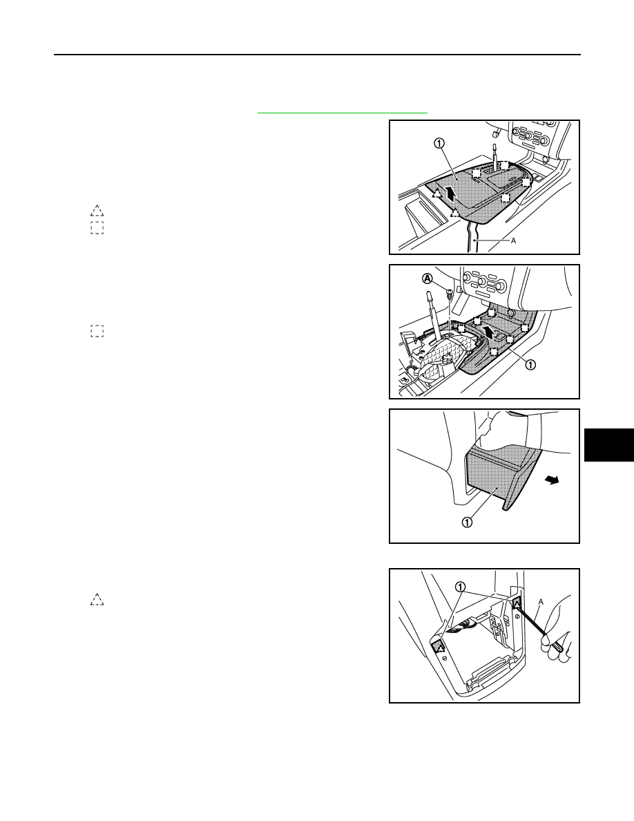
5.

Remove console rear finisher.
• Remove console mask (1) with flat-bladed screwdriver (A).

: Pawl

: Metal clip

JMJIA1334ZZ

: Metal clip

JMJIA1335ZZ

JMJIA1336ZZ

: Pawl

JMJIA1337ZZ

IP-22

< REMOVAL AND INSTALLATION >

CENTER CONSOLE ASSEMBLY

• Remove console rear finisher (2) fixing screws (A).
• Pull back console rear finisher.
• Disconnect harness connectors.

6.

Remove center console assembly.
• Remove center console assembly (1) fixing screws (A).
• Lift up back side and pull back.

7.

Remove instrument lower cover LH/RH.
• Disengage instrument lower cover LH (1) fixing pawls.
• Pull back instrument lower cover LH.
• Disengage instrument lower cover RH (2) fixing pawls and

clip.

• Pull the instrument lower cover RH crosswise.

8.

Remove lower console finisher LH/RH.
• Remove lower console finisher LH (1) fixing screws (A).
• Remove lower console finisher LH fixing clip (B).
• Remove lower console finisher LH fixing clip (C).
• Pull the console finisher LH crosswise.
• Remove lower console finisher RH (2) fixing screws (D).
• Remove lower console finisher RH fixing clip (E).
• Remove lower console finisher RH fixing clip (F).
• Pull the console finisher RH crosswise.

9.

Remove lower console assembly.
• Remove lower console assembly (1) fixing screws (A).
• Remove lower console assembly fixing bolts (B).
• Disconnect harness connectors.

: Metal clip

JMJIA1401ZZ

JMJIA1338ZZ

: Clip

: Pawl

JMJIA1339ZZ

: Clip

JMJIA1340ZZ

JMJIA1341ZZ

CENTER CONSOLE ASSEMBLY

IP-23

< REMOVAL AND INSTALLATION >

C

D

E

F

G

H

I

K

L

M

A

B

IP

N

O

P

10. Remove DVD player (if equipped). Refer to 

AV-538, "Removal and Installation"

.

11. Remove CVT shift selector. Refer to 

TM-162, "Removal and Installation"

.

12. Remove console reinforcement.

• Remove console reinforcement (1) fixing nuts (A).
• Remove console reinforcement fixing bolts (B).
• Remove harness clip.

13. Remove instrument stay LH fixing nuts, and then remove instrument stay LH.
14. Remove front console bracket fixing bolt and nuts, and then remove front console bracket.

INSTALLATION

Install in the reverse order of removal.

: Clip

JMJIA1342ZZ

LAN

LAN-1

ELECTRICAL & POWER CONTROL

C

D

E

F

G

H

I

J

K

L

B

SECTION 

LAN

A

O

P

N

CONTENTS

LAN SYSTEM

CAN FUNDAMENTAL

PRECAUTION ...............................................

6

PRECAUTIONS ...................................................

6

Precautions for Trouble Diagnosis  ............................

6

Precautions for Harness Repair  ................................

6

SYSTEM DESCRIPTION  ..............................

7

CAN COMMUNICATION SYSTEM  .....................

7

System Description  ...................................................

7

System Diagram ........................................................

7

CAN Communication Control Circuit .........................

8

DIAG ON CAN  .....................................................

9

Description ................................................................

9

System Diagram ........................................................

9

TROUBLE DIAGNOSIS  .....................................

10

Condition of Error Detection ....................................

10

Symptom When Error Occurs in CAN Communi-
cation System ..........................................................

10

CAN Diagnosis with CONSULT-III  ..........................

13

Self-Diagnosis .........................................................

14

CAN Diagnostic Support Monitor  ............................

14

How to Use CAN Communication Signal Chart  ......

16

BASIC INSPECTION  ...................................

17

DIAGNOSIS AND REPAIR WORKFLOW  .........

17

Trouble Diagnosis Flow Chart  .................................

17

Trouble Diagnosis Procedure ..................................

17

CAN

HOW TO USE THIS MANUAL .....................

22

HOW TO USE THIS SECTION ...........................

22

Caution ....................................................................

22

Abbreviation List ......................................................

22

PRECAUTION ..............................................

23

PRECAUTIONS .................................................

23

FOR USA AND CANADA  ..........................................

23

FOR USA AND CANADA : Precaution for Supple-
mental Restraint System (SRS) "AIR BAG" and 
"SEAT BELT PRE-TENSIONER" ............................

23

FOR USA AND CANADA : Precautions for Trou-
ble Diagnosis  ...........................................................

23

FOR USA AND CANADA : Precautions for Har-
ness Repair  .............................................................

23

FOR MEXICO .............................................................

24

FOR MEXICO : Precaution for Supplemental Re-
straint System (SRS) "AIR BAG" and "SEAT BELT 
PRE-TENSIONER" ..................................................

24

FOR MEXICO : Precautions for Trouble Diagnosis 

....

24

FOR MEXICO : Precautions for Harness Repair .....

25

BASIC INSPECTION  ...................................

26

DIAGNOSIS AND REPAIR WORKFLOW  ........

26

Interview Sheet ........................................................

26

SYSTEM DESCRIPTION  .............................

27

CAN COMMUNICATION SYSTEM  ...................

27

CAN System Specification Chart .............................

27

CAN Communication Signal Chart  ..........................

27

DTC/CIRCUIT DIAGNOSIS  .........................

31

CAN COMMUNICATION SYSTEM  ...................

31

Component Parts Location  ......................................

31

Wiring Diagram - CAN SYSTEM -  ...........................

32

MALFUNCTION AREA CHART ........................

41

Main Line  .................................................................

41

Branch Line  .............................................................

41

Short Circuit .............................................................

41

MAIN LINE BETWEEN ADP AND PWBD CIR-
CUIT ..................................................................

42


содержание   ..  946  947  948  949   ..