Murano Cross Cabriolet Z51 (2011 year). Manual - part 38


  Index      Manuals     Murano Cross Cabriolet Z51 (2011 year) - Service and Repair Manual


Search            copyright infringement  


Content      ..     36      37      38      39     ..


Murano Cross Cabriolet Z51 (2011 year). Manual - part 38


MIR-24

< SYMPTOM DIAGNOSIS >

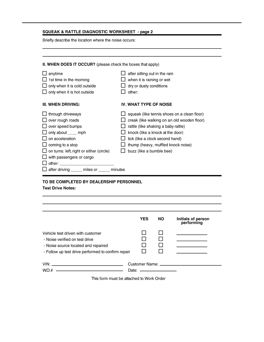
SQUEAK AND RATTLE TROUBLE DIAGNOSES

PIIB8742E

Revision: 2012 March

2011 Murano CrossCabriolet

INSIDE MIRROR

MIR-25

< REMOVAL AND INSTALLATION >

C

D

E

F

G

H

I

J

K

M

A

B

MIR

N

O

P

REMOVAL AND INSTALLATION

INSIDE MIRROR

Exploded View

INFOID:0000000007220989

Removal and Installation

INFOID:0000000007220990

REMOVAL

1.

Remove inside mirror cover.

2.

Disconnect harness connector from inside mirror. 

3.

Loosen TORX bolt and slide inside mirror upward to remove.

INSTALLATION

Install in the reverse order of removal.

1.

Windshield glass

2.

Inside mirror base

3.

Harness connector

4.

TORX bolt

5.

Inside mirror assembly

6.

Inside mirror cover 

N·m (kg·m, in-lb)

JMLIA0177GB

Revision: 2012 March

2011 Murano CrossCabriolet

MIR-26

< REMOVAL AND INSTALLATION >

DOOR MIRROR

DOOR MIRROR

Exploded View

INFOID:0000000007240449

DOOR MIRROR ASSEMBLY

DOOR MIRROR ASSEMBLY : Removal and Installation

INFOID:0000000007219725

CAUTION:

Never damage the mirror bodie.

REMOVAL

1.

Remove door finisher assembly. Refer to 

INT-13, "Removal and Installation"

.

2.

Remove door mirror corner cover (1).

a.

Disengage the fixing clips with a remover tool (A).

b.

Slide lightly door mirror corner cover toward the direction of the
arrow 1 to remove it from weather-strip (2).

c.

Slide door mirror corner cover toward the direction of the arrow
2 to disengage the fixing pawls and remove.

1.

Door mirror cover

2.

Door mirror

3.

Glass mirror

4.

Door mirror corner cover

5.

Clip

6.

Front door corner finisher

: Clip

: Pawl

: N·m (kg·m, in-lb)

JMLIA2270GB

: Clip

: Pawl

JMLIA2271ZZ

Revision: 2012 March

2011 Murano CrossCabriolet

DOOR MIRROR

MIR-27

< REMOVAL AND INSTALLATION >

C

D

E

F

G

H

I

J

K

M

A

B

MIR

N

O

P

3.

Remove door mirror assembly (2).

a.

Disconnect harness connector (A) and remove the mounting nuts (B).

b.

Remove weather-strip (1) from door mirror assembly and pull out toward the direction of the arrow to 
remove.

INSTALLATION

Install in the reverse order of removal.

GLASS MIRROR

GLASS MIRROR : Removal and Installation

INFOID:0000000007219727

CAUTION:

Never damage the mirror bodies.

DISASSEMBLY

1.

Place the glass mirror (1) upward.

2.

Insert flat-bladed screwdriver (B) into the recess at lower side
between glass mirror and actuator and push up pawls to remove
glass.

CAUTION:

Put a strip of protective tape (A) on the housing.
NOTE:
Insert a flat-bladed screwdriver into recess, and push up while
rotating (twist) to make work easier.

3.

Insert flat-bladed screwdriver at left and right side between glass mirror and actuator, and push up pawls
to remove glass mirror.
NOTE:
Insert flat-bladed screwdriver into recesses, and push up while rotating (twist) to make work easier.

4.

Disconnect both terminals (A) of mirror heater attachment. (With
heater mirror model)

5.

Remove glass mirror from actuator.

ASSEMBLY

Install in the reverse order of removal.

CAUTION:

After installation, visually check that pawls are securely engaged.

JMLIA2272ZZ

JMLIA2273ZZ

JMLIA2274ZZ

Revision: 2012 March

2011 Murano CrossCabriolet

MIR-28

< REMOVAL AND INSTALLATION >

DOOR MIRROR

DOOR MIRROR COVER

DOOR MIRROR COVER : Removal and Installation

INFOID:0000000007219729

CAUTION:

Never damage the mirror bodie.

DISASSEMBLY

1.

Remove glass mirror. Refer to 

MIR-27, "GLASS MIRROR : Removal and Installation"

.

2.

Remove the actuator fixing screws (A) and then remove the
actuator.

3.

Disengage the door mirror cover fixing pawls (A) and remove the door mirror cover from housing.

ASSEMBLY

Install in the reverse order of removal.
NOTE:
After installation, visually check that pawls are securely engaged.

FRONT DOOR CORNER FINISHER

FRONT DOOR CORNER FINISHER : Removal and Installation

INFOID:0000000007236378

REMOVAL

Remove front door corner finisher (1).
Insert a remover tool (A) between body panel and front door corner
finisher to disengage the fixing clips and pawl.

CAUTION:

Put a strip of protective tape on body panel to protect it from
damage. 

INSTALLATION

CAUTION:

JMLIA2276ZZ

: Pawl

JMLIA2277ZZ

: Clip

: Pawl

JMKIA2261ZZ

Revision: 2012 March

2011 Murano CrossCabriolet

DOOR MIRROR

MIR-29

< REMOVAL AND INSTALLATION >

C

D

E

F

G

H

I

J

K

M

A

B

MIR

N

O

P

• When installing, check visually front door corner finisher fixing pawl and clips then replace them

with new parts if they have been damaged.

• When installing front door corner finisher, check that pawl and clips are securely fitted in door panel,

and then press pawls in.

Revision: 2012 March

2011 Murano CrossCabriolet

MIR-30

< REMOVAL AND INSTALLATION >

DOOR MIRROR REMOTE CONTROL SWITCH

DOOR MIRROR REMOTE CONTROL SWITCH

Removal and Installation

INFOID:0000000007219731

REMOVAL

1.

Remove the power window main switch finisher (2). Refer to

INT-13, "Removal and Installation"

2.

Remove door mirror remote control switch (1) from power win-
dow main switch finisher (2) using flat-bladed screwdriver (A).

INSTALLATION

Install in the reverse order of removal.

: Pawl

JMLIA0118ZZ

Revision: 2012 March

2011 Murano CrossCabriolet

PB-1

BRAKES

C

D

E

G

H

I

J

K

L

M

SECTION 

PB

A

B

PB

N

O

P

CONTENTS

PARKING BRAKE SYSTEM

PREPARATION ............................................

2

PREPARATION ...................................................

2

Commercial Service Tool  ..........................................

2

PERIODIC MAINTENANCE ..........................

3

PARKING BRAKE SYSTEM  ...............................

3

Inspection and Adjustment ........................................

3

PARKING BRAKE SHOE  ...................................

5

Adjustment ................................................................

5

REMOVAL AND INSTALLATION ................

6

PARKING BRAKE CONTROL  ............................

6

Exploded View  ..........................................................

6

Removal and Installation  ..........................................

6

Adjustment ................................................................

7

PARKING BRAKE SHOE  ..................................

8

Exploded View ..........................................................

8

Removal and Installation  ..........................................

8

Inspection and Adjustment  .......................................

9

SERVICE DATA AND SPECIFICATIONS 
(SDS) ............................................................

11

SERVICE DATA AND SPECIFICATIONS 
(SDS) .................................................................

11

Parking Drum Brake  ................................................

11

Parking Brake Control  .............................................

11

Revision: 2012 March

2011 Murano CrossCabriolet

PB-2

< PREPARATION >

PREPARATION

PREPARATION

PREPARATION

Commercial Service Tool

INFOID:0000000006940194

Tool name

Description

Power tool

Loosening bolts and nuts

PBIC0190E

Revision: 2012 March

2011 Murano CrossCabriolet

PARKING BRAKE SYSTEM

PB-3

< PERIODIC MAINTENANCE >

C

D

E

G

H

I

J

K

L

M

A

B

PB

N

O

P

PERIODIC MAINTENANCE

PARKING BRAKE SYSTEM

Inspection and Adjustment

INFOID:0000000006940195

INSPECTION

Pedal Stroke

1.

Operate the parking brake pedal with a force of 196 N (20 kg, 44 lb). Check that the pedal stroke is within
the specified number of notches. (Check it by listening to the clicks of the ratchet.)

2.

When brake warning lamp turns ON, check that the pedal stroke is within the specified number of
notches. (Check it by listening to the clicks of the ratchet.)

Inspect Components

• Check each component for installation condition such as looseness.
• Check the parking brake pedal assembly for bend, damage and cracks. Replace if necessary.
• Check the cables for wear, damage and cracks. Replace if necessary.
• Check the parking brake switch, and replace it if necessary. Refer to 

BRC-83, "Component Inspection"

.

ADJUSTMENT

1.

Fix the disc rotor using wheel nuts.

2.

Remove fuse block lid. Refer to 

IP-12, "Exploded View"

.

3.

Release the parking brake pedal (1) by turning the adjusting nut
(2) with a deep socket wrench and loosening the cable.

4.

Remove the adjusting hole plug from the disc rotor. Turn the
adjuster (1) in the direction (A) as shown in the figure using a
suitable tool until the disc rotor is locked. 

5.

Turn back the adjuster 5 or 6 notches from the locked position.

6.

Rotate the disc rotor to check that there is no drag. Install the
adjusting hole plug.

7.

Adjust the cable with the following procedure.

a.

Operate the parking brake pedal with a force of 490 N (50 kg,
110 lb) for 10 strokes or more. 

b.

Adjust the parking brake pedal stroke by turning the adjusting
nut with a deep socket wrench.

CAUTION:

Never reuse the adjusting nut if the nut is removed.

c.

Operate the parking brake pedal with a force of 196 N (20 kg, 44 lb). Check that the pedal stroke is within
the specified number of notches. (Check it by listening to the clicks of the ratchet.)

Standard

Number of notches

: Refer to 

PB-11, "Parking Brake Control"

.

Standard

Number of notches

: Refer to 

PB-11, "Parking Brake Control"

.

JPFIB0044ZZ

JPFIB0002ZZ

Revision: 2012 March

2011 Murano CrossCabriolet

PB-4

< PERIODIC MAINTENANCE >

PARKING BRAKE SYSTEM

d.

Rotate the disc rotor with the parking brake pedal released and check that there is no drag. Refer to 

PB-9,

"Inspection and Adjustment"

.

Standard

Number of notches

: Refer to 

PB-11, "Parking Brake Control"

.

Revision: 2012 March

2011 Murano CrossCabriolet

PARKING BRAKE SHOE

PB-5

< PERIODIC MAINTENANCE >

C

D

E

G

H

I

J

K

L

M

A

B

PB

N

O

P

PARKING BRAKE SHOE

Adjustment

INFOID:0000000006940196

1.

Adjust parking brake pedal stroke. Refer to 

PB-3, "Inspection and Adjustment"

.

2.

Perform parking brake break-in (drag on) operation by driving vehicle under the following conditions: 
• Drive forward
• Vehicle speed: Approx. 40 km/h (25 MPH) set (constant and forward)
• Parking brake operating force: Approx. 145 N (15 kg, 33 lb)
• Time: Approx. 10 sec.

CAUTION:

To prevent lining from getting too hot, allow a cool off period of approximately 5 minutes after
every break-in operation.

3.

After the break-in procedure, check parking pedal stroke of parking brake.

CAUTION:

If it is out of the specification, adjust again. Refer to 

PB-3, "Inspection and Adjustment"

.

Revision: 2012 March

2011 Murano CrossCabriolet

PB-6

< REMOVAL AND INSTALLATION >

PARKING BRAKE CONTROL

REMOVAL AND INSTALLATION

PARKING BRAKE CONTROL

Exploded View

INFOID:0000000006940197

Removal and Installation

INFOID:0000000006940198

REMOVAL

1.

Remove rear tires with power tool.

2.

Remove instrument panel assembly. Refer to 

IP-12, "Exploded View"

.

3.

Disconnect parking brake switch harness connector.

4.

Remove adjusting nut and loosen front cable.

5.

Remove parking brake pedal assembly.

6.

Remove rear ventilator duct. Refer to 

VTL-7, "Exploded View"

.

7.

Separate front cable from rear cable, and remove front cable and return spring.

8.

Remove parking brake shoe, and remove rear cable from toggle lever. Refer to 

PB-8, "Exploded View"

.

9.

Remove rear cable mounting bolts and nuts, pull out rear cable from vehicle.

INSTALLATION

Note the following, Install the reverse order of the removal.
• Never reuse the adjusting nut.

1.

Pin

2.

Rear cable (RH)

3.

Rear cable (LH)

4.

Return spring

5.

Front cable

6.

Parking brake switch

7.

Stopper rubber

8.

Return spring

9.

Silencer

10. Parking brake pedal assembly

11.

Pedal pad

12. Adjusting nut

: Apply multi-purpose grease.

Refer to 

GI-4, "Components"

 for symbols not described on the above.

JPFIB0056GB

Revision: 2012 March

2011 Murano CrossCabriolet

PARKING BRAKE CONTROL

PB-7

< REMOVAL AND INSTALLATION >

C

D

E

G

H

I

J

K

L

M

A

B

PB

N

O

P

Adjustment

INFOID:0000000006940199

ADJUSTMENT AFTER INSTALLATION

Adjust the parking brake pedal stroke. Refer to 

PB-3, "Inspection and Adjustment"

.

Revision: 2012 March

2011 Murano CrossCabriolet

PB-8

< REMOVAL AND INSTALLATION >

PARKING BRAKE SHOE

PARKING BRAKE SHOE

Exploded View

INFOID:0000000006940200

Removal and Installation

INFOID:0000000006940201

REMOVAL

WARNING:

Since dust covering the parking brake has an affect on human body, the dust must be removed with a
dust collector. Never splatter the dust with an air blow gun.

1.

Remove rear tires with power tool.

2.

Remove disc rotor. Refer to 

BR-41, "BRAKE CALIPER ASSEMBLY : Removal and Installation"

.

CAUTION:

Parking brake completely in the released position.

3.

If disc rotor cannot be removed, remove as follows:

a.

Fix the disc rotor with wheel nuts and remove the adjusting hole plug.

b.

Using suitable tool, rotate adjuster (1) in direction (B) to retract
and loosen parking brake shoe.

4.

Remove anti-rattle pins, retainers, anti-rattle spring, adjuster
spring and return springs.

CAUTION:

Never drop the removed parts.

5.

Remove parking brake shoes, adjuster assembly and toggle
lever.

CAUTION:

• The parking brake shoes for the front side are made of dif-

ferent materials from those for the rear side. Never misi-
dentify them when removing.

• Never drop the removed parts.

INSTALLATION

Install in the reverse order of removal.
• Apply PBC (Poly Butyl Cuprysil) grease or silicone-based grease to the back plate and brake shoe.

1.

Back plate

2.

Parking brake shoe

3.

Adjuster

4.

Adjuster spring

5.

Return spring

6.

Anti-rattle spring

7.

Retainer

8.

Anti-rattle pin

9.

Toggle lever

: Apply PBC (Poly Butyl Cuprysil) grease or silicone-based grease.

JPFIB0046ZZ

JPFIB0007ZZ

Revision: 2012 March

2011 Murano CrossCabriolet

PARKING BRAKE SHOE

PB-9

< REMOVAL AND INSTALLATION >

C

D

E

G

H

I

J

K

L

M

A

B

PB

N

O

P

CAUTION:

The parking brake shoes for the front side are made of different materials from those for the rear
side. Never misidentify them when removing and replacing.

• Assemble adjusters so that threaded part is expanded when rotat-

ing it in the direction shown by arrow.

• Shorten adjuster by rotating it.
• When disassembling, apply PBC (Poly Butyl Cuprysil) grease or

silicone-based grease to threads.

• Check parking brake shoe sliding surface and drum inner surface

for grease. Wipe it off if it adhere on the surfaces.

Inspection and Adjustment

INFOID:0000000006940202

INSPECTION

Brake Lining Thickness Inspection

• Check thickness (A) of brake lining.

Drum Inner Diameter Inspection

• Check inner diameter (B) of drum. 

Other Inspections

• Check brake lining for excessive wear, damage, and peeling. Replace if necessary.
• Check parking brake shoe sliding surface for excessive wear and damage. Replace if necessary.
• Check anti-rattle pin and retainer for excessive wear, damage and rust. Replace if necessary.
• Check adjuster spring, anti-rattle spring and return springs for settling, excessive wear, damage, and rust.

Replace if necessary.

• Check adjuster for smoothness. Replace if necessary.
• Check toggle lever for excessive wear, damage and rust. Replace if necessary.
• Visually check inside of the drum for excessive wear, cracks, and damage with a pair of vernier calipers.

Replace if necessary.

ADJUSTMENT

1.

Adjust the parking brake pedal stroke. Refer to 

PB-3, "Inspection and Adjustment"

.

2.

Check a drag of the parking brake.

A

:  For  RH  brake

B

: For LH brake

: Vehicle front

: Adjuster expands

JPFIB0009ZZ

Limit

A

:  Refer  to 

PB-11, "Parking Drum Brake"

.

SBR021A

Limit

B

: Refer to 

PB-11, "Parking Drum Brake"

.

JPFIB0008ZZ

Revision: 2012 March

2011 Murano CrossCabriolet


Content      ..     36      37      38      39     ..