Nissan Murano Z50 (2005 year). Manual - part 175
CAN SYSTEM (TYPE 10)
LAN-413
[CAN]
C
D
E
F
G
H
I
J
L
M
A
B
LAN
Revision: 2005 August
2005 Murano
2.
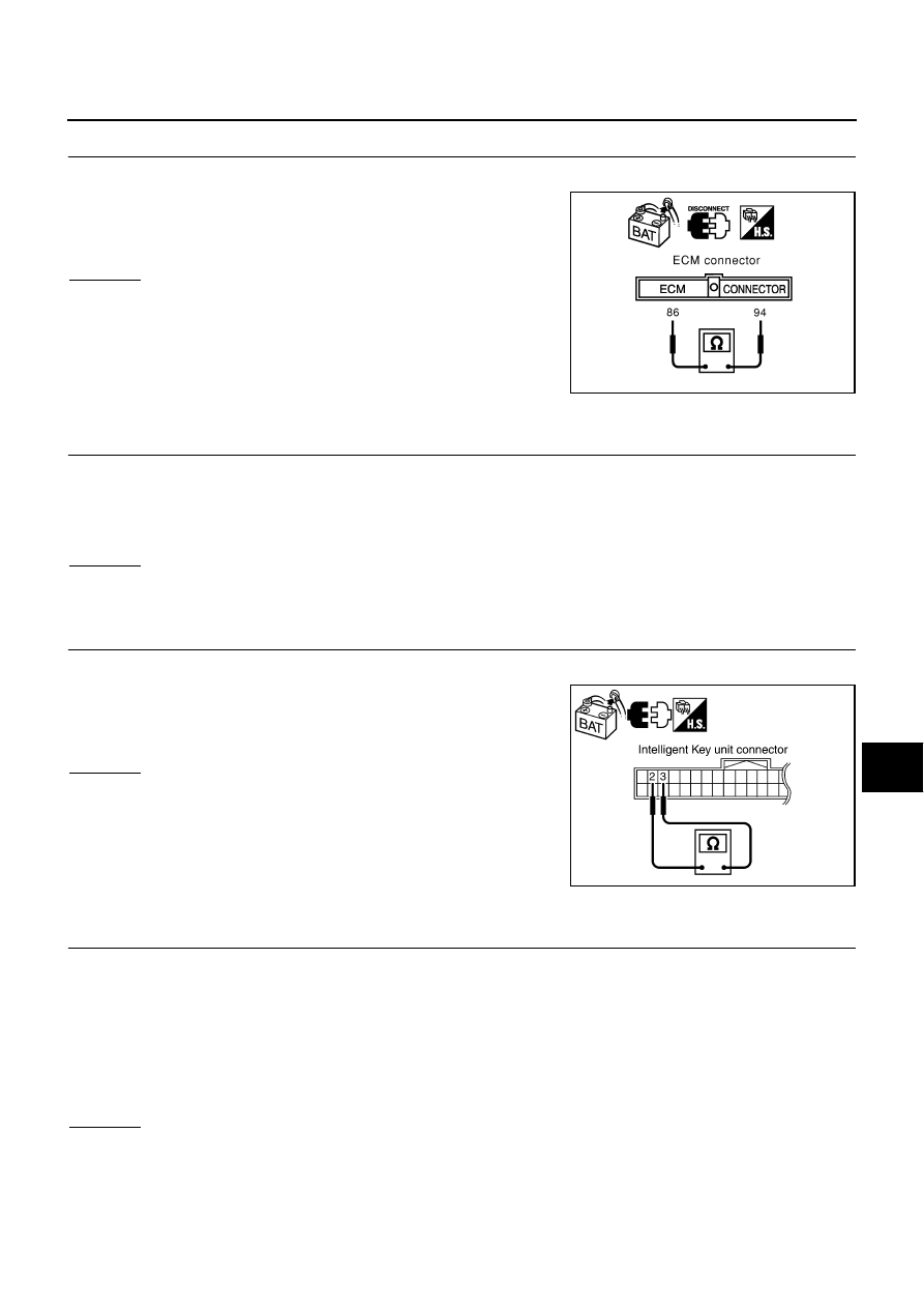
CHECK HARNESS FOR OPEN CIRCUIT
1.
Disconnect ECM connector.
2.
Check resistance between ECM harness connector M80 termi-
nals 94 (L) and 86 (Y).
OK or NG
OK
>> Replace ECM.
NG
>> Repair harness between ECM and BCM.
Intelligent Key Unit Circuit Inspection
AKS00CHZ
1.
CHECK CONNECTOR
1.
Turn ignition switch OFF.
2.
Disconnect the battery cable from the negative terminal.
3.
Check terminals and connector of Intelligent Key unit for damage, bend and loose connection (control
module side and harness side).
OK or NG
OK
>> GO TO 2.
NG
>> Repair terminal or connector.
2.
CHECK HARNESS FOR OPEN CIRCUIT
1.
Disconnect Intelligent Key unit connector.
2.
Check resistance between Intelligent Key unit harness connec-
tor M99 terminals 2 (L) and 3 (Y).
OK or NG
OK
>> Replace Intelligent Key unit.
NG
>> Repair harness between Intelligent Key unit and BCM.
TCM Circuit Inspection
AKS00CI0
1.
CHECK CONNECTOR
1.
Turn ignition switch OFF.
2.
Disconnect the battery cable from the negative terminal.
3.
Check following terminals and connectors for damage, bend and loose connection (control module side
and harness side).
–
TCM connector
–
Harness connector F102
–
Harness connector M82
OK or NG
OK
>> GO TO 2.
NG
>> Repair terminal or connector.
94 (L) - 86 (Y)
: Approx. 108 - 132
Ω
SKIA6865E
2 (L) - 3 (Y)
: Approx. 54 - 66
Ω
PKIB5312E