Nissan Murano Z50 (2005 year). Manual - part 174
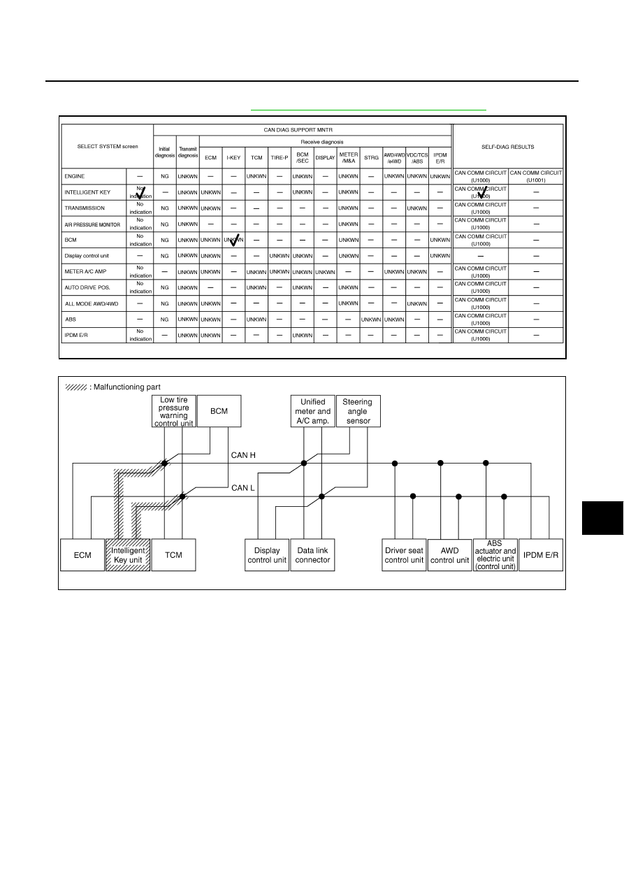
CAN SYSTEM (TYPE 10)
LAN-397
[CAN]
C
D
E
F
G
H
I
J
L
M
A
B
LAN
Revision: 2005 August
2005 Murano
Case 6
Check Intelligent Key unit circuit. Refer to
LAN-413, "Intelligent Key Unit Circuit Inspection"
.
PKIB4891E
PKIB4679E