Nissan Murano Z50 (2005 year). Manual - part 88


  Index      Manuals     Nissan Murano Z50 (2005 year) - Service and Repair Manual


Search            copyright infringement  


Content      ..     86      87      88      89     ..


Nissan Murano Z50 (2005 year). Manual - part 88


POWER SUPPLY AND GROUND CIRCUIT

EC-163

C

D

E

F

G

H

I

J

K

L

M

A

EC

Revision: 2005 August

2005 Murano

8. 

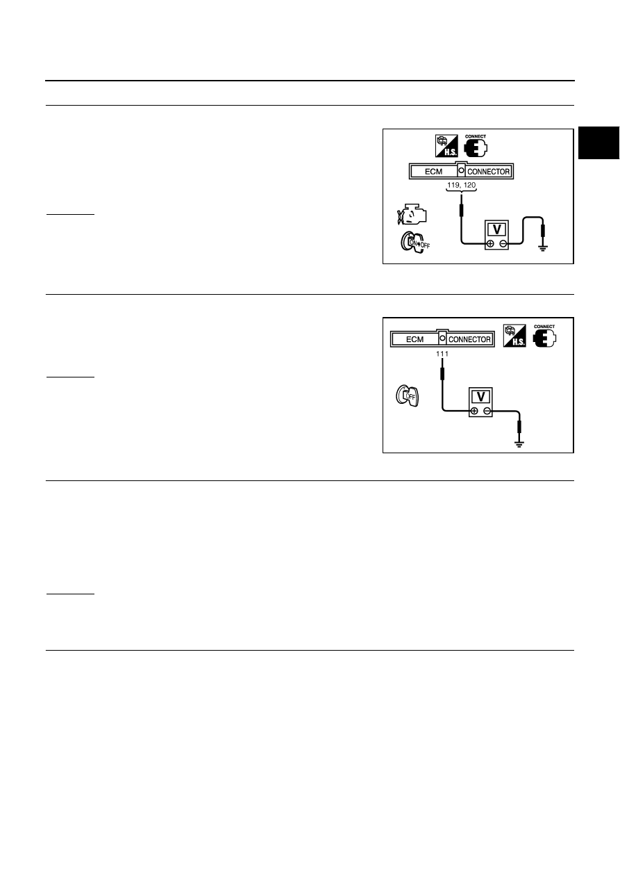
CHECK ECM POWER SUPPLY CIRCUIT-III

1.

Turn ignition switch OFF and wait at least 10 seconds.

2.

Check voltage between ECM terminals 119, 120 and ground
with CONSULT-II or tester.

OK or NG

OK

>> GO TO 15.

NG (Battery voltage does not exist.)>>GO TO 9.
NG (Battery voltage exists for more than a few seconds.)>>GO  TO

12.

9. 

CHECK ECM POWER SUPPLY CIRCUIT-V

1.

Turn ignition switch OFF.

2.

Check voltage between ECM terminal 111 and ground with
CONSULT-II or tester.

OK or NG

OK

>> GO TO 10.

NG

>> GO TO 12.

10. 

CHECK ECM POWER SUPPLY CIRCUIT-VI

1.

Disconnect ECM harness connector.

2.

Disconnect IPDM E/R harness connector E7.

3.

Check harness continuity between ECM terminals 119, 120 and IPDM E/R terminal 18.
Refer to Wiring Diagram.

4.

Also check harness for short to ground and short to power.

OK or NG

OK

>> GO TO 18.

NG

>> GO TO 11.

11. 

DETECT MALFUNCTIONING PART

Check the following.

Harness or connectors E110, M7

Harness for open or short between ECM and IPDM E/R

>> Repair open circuit or short to ground or short to power in harness or connectors.

Voltage:

After turning ignition switch OFF, battery 
voltage will exist for a few seconds, then 
drop approximately 0V.

PBIB1630E

Voltage: Battery voltage

PBIB1191E

Continuity should exist.

EC-164

POWER SUPPLY AND GROUND CIRCUIT

Revision: 2005 August

2005 Murano

12. 

CHECK ECM POWER SUPPLY CIRCUIT-VII

1.

Disconnect ECM harness connector.

2.

Disconnect IPDM E/R harness connector E9.

3.

Check harness continuity between ECM terminal 111 and IPDM E/R terminal 46.
Refer to Wiring Diagram.

4.

Also check harness for short to ground and short to power.

OK or NG

OK

>> GO TO 14.

NG

>> GO TO 13.

13. 

DETECT MALFUNCTIONING PART

Check the following.

Harness or connectors E110, M7

Harness for open or short between ECM and IPDM E/R

>> Repair open circuit or short to ground or short to power in harness or connectors.

14. 

CHECK 15A FUSE

1.

Disconnect 15A fuse from IPDM E/R.

2.

Check 15A fuse.

OK or NG

OK

>> GO TO 18.

NG

>> Replace 15A fuse.

15. 

CHECK GROUND CONNECTIONS

Loosen and retighten two ground screws on the body.
Refer to 

EC-166, "Ground Inspection"

 .

OK or NG

OK

>> GO TO 16.

NG

>> Repair or replace ground connections.

Continuity should exist.

PBIB1835E

POWER SUPPLY AND GROUND CIRCUIT

EC-165

C

D

E

F

G

H

I

J

K

L

M

A

EC

Revision: 2005 August

2005 Murano

16. 

CHECK ECM GROUND CIRCUIT FOR OPEN AND SHORT-II

1.

Disconnect ECM harness connector.

2.

Check harness continuity between ECM terminals 1, 115, 116 and ground.
Refer to Wiring Diagram.

3.

Also check harness for short to power.

OK or NG

OK

>> GO TO 18.

NG

>> GO TO 17.

17. 

DETECT MALFUNCTIONING PART

Check the following.

Harness connectors F102, M82

Harness for open or short between ECM and ground

>> Repair open circuit or short to power in harness or connectors.

18. 

CHECK INTERMITTENT INCIDENT

Refer to 

EC-157, "TROUBLE DIAGNOSIS FOR INTERMITTENT INCIDENT"

 .

OK or NG

OK

>> Replace IPDM E/R.

NG

>> Repair open circuit or short to ground or short to power in harness or connectors.

Continuity should exist.

EC-166

POWER SUPPLY AND GROUND CIRCUIT

Revision: 2005 August

2005 Murano

Ground Inspection

ABS00D9L

Ground connections are very important to the proper operation of electrical and electronic circuits. Ground
connections are often exposed to moisture, dirt and other corrosive elements. The corrosion (rust) can
become an unwanted resistance. This unwanted resistance can change the way a circuit works.
Electronically controlled circuits are very sensitive to proper grounding. A loose or corroded ground can drasti-
cally affect an electronically controlled circuit. A poor or corroded ground can easily affect the circuit. Even
when the ground connection looks clean, there can be a thin film of rust on the surface.
When inspecting a ground connection follow these rules:

Remove the ground bolt or screw.

Inspect all mating surfaces for tarnish, dirt, rust, etc.

Clean as required to assure good contact.

Reinstall bolt or screw securely.

Inspect for “add-on” accessories which may be interfering with the ground circuit.

If several wires are crimped into one ground eyelet terminal, check for proper crimps. Make sure all of the
wires are clean, securely fastened and providing a good ground path. If multiple wires are cased in one
eyelet make sure no ground wires have excess wire insulation.

For detailed ground distribution information, refer to 

PG-30, "Ground Distribution"

 .

PBIB1870E

DTC U1000, U1001 CAN COMMUNICATION LINE

EC-167

C

D

E

F

G

H

I

J

K

L

M

A

EC

Revision: 2005 August

2005 Murano

DTC U1000, U1001 CAN COMMUNICATION LINE

PFP:23710

Description

ABS004BD

CAN (Controller Area Network) is a serial communication line for real time application. It is an on-vehicle mul-
tiplex communication line with high data communication speed and excellent error detection ability. Many elec-
tronic control units are equipped onto a vehicle, and each control unit shares information and links with other
control units during operation (not independent). In CAN communication, control units are connected with 2
communication lines (CAN H line, CAN L line) allowing a high rate of information transmission with less wiring.
Each control unit transmits/receives data but selectively reads required data only.

On Board Diagnosis Logic

ABS004BE

*1: This self-diagnosis has the one trip detection logic.
*2: The MIL will not light up for this diagnosis.

DTC Confirmation Procedure

ABS004BF

1.

Turn ignition switch ON and wait at least 3 seconds.

2.

Select “DATA MONITOR” mode with CONSULT-II.

3.

If 1st trip DTC is detected, go to 

EC-169, "Diagnostic Procedure"

 .

DTC No.

Trouble diagnosis 

name

DTC detecting condition

Possible cause

U1000*

1

1000*

1

CAN communication 
line

ECM cannot communicate to other control 
units.

ECM cannot communicate for more than the 
specified time.

Harness or connectors
(CAN communication line is open or 
shorted)

U1001*

2

1001*

2

EC-168

DTC U1000, U1001 CAN COMMUNICATION LINE

Revision: 2005 August

2005 Murano

Wiring Diagram

ABS004BG

TBWA0343E

DTC U1000, U1001 CAN COMMUNICATION LINE

EC-169

C

D

E

F

G

H

I

J

K

L

M

A

EC

Revision: 2005 August

2005 Murano

Diagnostic Procedure

ABS004V8

Go to 

LAN-5, "Precautions When Using CONSULT-II"

 .

EC-170

DTC P0011, P0021 IVT CONTROL

Revision: 2005 August

2005 Murano

DTC P0011, P0021 IVT CONTROL

PFP:23796

Description

ABS004BI

SYSTEM DESCRIPTION

*: This signal is sent to the ECM through CAN Communication line 

This mechanism hydraulically controls cam phases continuously with the fixed operating angle of the intake
valve.
The ECM receives signals such as crankshaft position, camshaft position, engine speed, and engine coolant
temperature. Then, the ECM sends ON/OFF pulse duty signals to the intake valve timing control solenoid
valve depending on driving status. This makes it possible to control the shut/open timing of the intake valve to
increase engine torque in low/mid speed range and output in high-speed range.

CONSULT-II Reference Value in Data Monitor Mode

ABS004BJ

Specification data are reference values.

Sensor

Input signal to ECM

ECM function

Actuator

Crankshaft position sensor (POS)

Engine speed and piston position

Intake valve 
timing control

Intake valve timing control 
solenoid valve

Camshaft position sensor (PHASE)

Engine coolant temperature sensor

Engine coolant temperature

Wheel sensor*

Vehicle speed

PBIB1389E

MONITOR ITEM

CONDITION

SPECIFICATION

INT/V TIM (B1)
INT/V TIM (B2)

Engine: After warming up

Shift lever: P or N

Air conditioner switch: OFF

No-load

Idle

5

°

 - 5

°

CA

2,000 rpm

Approx. 0

°

 - 30

°

CA

INT/V SOL (B1)
INT/V SOL (B2)

Engine: After warming up

Shift lever: P or N

Air conditioner switch: OFF

No-load

Idle

0% - 2%

2,000 rpm

Approx. 0% - 50%

DTC P0011, P0021 IVT CONTROL

EC-171

C

D

E

F

G

H

I

J

K

L

M

A

EC

Revision: 2005 August

2005 Murano

On Board Diagnosis Logic

ABS004BK

FAIL-SAFE MODE

When the malfunction is detected, the ECM enters fail-safe mode.

DTC Confirmation Procedure

ABS004BL

CAUTION:

Always drive at a safe speed.

NOTE:

If DTC P0011 or P0021 is displayed with DTC P1111 or P1136, first perform trouble diagnosis for
DTC P1111 or P1136. Refer to 

EC-413

 .

If DTC Confirmation Procedure has been previously conducted, always turn ignition switch OFF and wait
at least 10 seconds before conducting the next test. 

TESTING CONDITION:
Before performing the following procedure, confirm that battery voltage is between 10V and 16V at
idle.

 WITH CONSULT-II

1.

Turn ignition switch ON and select “DATA MONITOR” mode with
CONSULT-II.

2.

Start engine and warm it up to the normal operating tempera-
ture.

3.

Maintain the following conditions for at least 6 consecutive sec-
onds.
Hold the accelerator pedal as steady as possible.

4.

Let engine idle for 10 seconds.

5.

If the 1st trip DTC is detected, go to 

EC-172, "Diagnostic Procedure"

 .

If the 1st trip DTC is not detected, go to next step.

6.

Maintain the following conditions for at least 20 consecutive seconds.

7.

If the 1st trip DTC is detected, go to 

EC-172, "Diagnostic Procedure"

 .

DTC No.

Trouble diagnosis 

name

Detecting condition

Possible cause

P0011
0011
(Bank 1)

Intake valve timing 
control performance

There is a gap between angle of target and 
phase-control angle degree.

Crankshaft position sensor (POS)

Camshaft position sensor (PHASE)

Intake valve control solenoid valve

Accumulation of debris to the signal pick-up 
portion of the camshaft

Timing chain installation

Foreign matter caught in the oil groove for 
intake valve timing control

P0021
0021
(Bank 2)

Detected items

Engine operating condition in fail-safe mode

Intake valve timing control

The signal is not energized to the solenoid valve and the valve control does not function.

ENG SPEED

1,200 - 2,000 rpm (A constant rotation is maintained.)

COOLAN TEMP/S

60 - 120

°

C (140 - 248

°

F)

Selector lever

P or N position

ENG SPEED

1,700 - 3,175 rpm (A constant rotation is maintained.)

COOLAN TEMP/S

70 - 105

°

C (158 - 221

°

F)

Selector lever

1st or 2nd position

Driving location uphill

Driving vehicle uphill
(Increased engine load will help maintain the driving 
conditions required for this test.)

PBIB0164E

EC-172

DTC P0011, P0021 IVT CONTROL

Revision: 2005 August

2005 Murano

 WITH GST

Follow the procedure “WITH CONSULT-II” above.

Diagnostic Procedure

ABS004BM

1. 

CHECK OIL PRESSURE WARNING LAMP

1.

Start engine.

2.

Check oil pressure warning lamp and confirm it is not illumi-
nated.

OK or NG

OK

>> GO TO 2.

KG

>> Go to 

LU-7, "OIL PRESSURE CHECK"

 .

2. 

CHECK INTAKE VALVE TIMING CONTROL SOLENOID VALVE

Refer to 

EC-173, "Component Inspection"

 .

OK or NG

OK

>> GO TO 3.

NG

>> Replace intake valve timing control solenoid valve.

3. 

CHECK CRANKSHAFT POSITION SENSOR (POS)

Refer to 

EC-303, "Component Inspection"

 .

OK or NG

OK

>> GO TO 4.

NG

>> Replace crankshaft position sensor (POS).

4. 

CHECK CAMSHAFT POSITION SENSOR (PHASE)

Refer to 

EC-312, "Component Inspection"

 .

OK or NG

OK

>> GO TO 5.

NG

>> Replace camshaft position sensor (PHASE).

5. 

CHECK CAMSHAFT (INTAKE)

Check the following.

Accumulation of debris to the signal plate of camshaft rear end

Chipping signal plate of camshaft rear end

OK or NG

OK

>> GO TO 6.

NG

>> Remove debris and clean the signal plate of camshaft

rear end or replace camshaft.

PBIA8559J

SEC905C

DTC P0011, P0021 IVT CONTROL

EC-173

C

D

E

F

G

H

I

J

K

L

M

A

EC

Revision: 2005 August

2005 Murano

6. 

CHECK TIMING CHAIN INSTALLATION

Check service records for any recent repairs that may cause timing chain misaligned.
Are there any service records that may cause timing chain misaligned?

Yes or No

Yes

>> Check timing chain installation. Refer to 

EM-60, "TIMING CHAIN"

 .

No

>> GO TO 7.

7. 

CHECK LUBRICATION CIRCUIT

Refer to 

EM-81, "INSPECTION AFTER REMOVAL"

 .

OK or NG

OK

>> GO TO 8.

NG

>> Clean lubrication line.

8. 

CHECK INTERMITTENT INCIDENT

Refer to 

EC-157, "TROUBLE DIAGNOSIS FOR INTERMITTENT INCIDENT"

 .

For wiring diagram, refer to 

EC-299

   for CKP sensor (POS), 

EC-306

   an

EC-308

   for CMP sensor (PHASE).

>> INSPECTION END

Component Inspection

ABS00E8U

INTAKE VALVE TIMING CONTROL SOLENOID VALVE

1.

Disconnect intake valve timing control solenoid valve harness connector.

2.

Check resistance between intake valve timing control solenoid
valve as follows.

If NG, replace intake valve timing control solenoid valve.
If OK, go to next step.

3.

Remove intake valve timing control solenoid valve.

4.

Provide 12V DC between intake valve timing control solenoid
valve terminals and then interrupt it. Make sure that the plunger
moves as shown in the figure.

CAUTION:

Do not apply 12V DC continuously for 5 seconds or more.
Doing so may result in damage to the coil in intake valve
timing control solenoid valve.
If NG, replace intake valve timing control solenoid valve.

NOTE:
Always replace O-ring when intake valve timing control
solenoid valve is removed.

Removal and Installation

ABS00E8V

INTAKE VALVE TIMING CONTROL SOLENOID VALVE

Refer to 

EM-60, "TIMING CHAIN"

 .

Terminal

Resistance

1 and 2

7.0 - 7.5

 at 20

°

C (68

°

F)

1 or 2 and ground

∞Ω

 (Continuity should not exist.)

PBIB0193E

PBIB2275E

EC-174

DTC P0037, P0038, P0057, P0058 HO2S2 HEATER

Revision: 2005 August

2005 Murano

DTC P0037, P0038, P0057, P0058 HO2S2 HEATER

PFP:226A0

Description

ABS004BV

SYSTEM DESCRIPTION

The ECM performs ON/OFF control of the heated oxygen sensor 2 heater corresponding to the engine speed,
amount of intake air and engine coolant temperature. 

OPERATION

CONSULT-II Reference Value in Data Monitor Mode

ABS004BW

Specification data are reference values.

On Board Diagnosis Logic

ABS004BX

Sensor

Input signal to ECM

ECM function

Actuator

Camshaft position sensor (PHASE)

Engine speed

Heated oxygen sensor 2 
heater control

Heated oxygen sensor 2 heater

Crankshaft position sensor (POS)

Engine coolant temperature sensor

Engine coolant temperature

Mass air flow sensor

Amount of intake air

Engine speed rpm

Heated oxygen sensor 2 heater

Above 3,600

OFF

Below 3,600 rpm after the following conditions are met.

Engine: After warming up

Keeping the engine speed between 3,500 and 4,000 rpm for 1 
minute and at idle for 1 minute under no load

ON

MONITOR ITEM

CONDITION

SPECIFICATION

HO2S2 HTR (B1)
HO2S2 HTR (B2)

Engine speed is below 3,600 rpm after the following conditions are met.

Engine: After warming up

Keeping the engine speed between 3,500 and 4,000 rpm for 1 minute and 
at idle for 1 minute under no load

ON

Engine speed: Above 3,600 rpm

OFF

DTC No.

Trouble diagnosis 

name

DTC detecting condition

Possible cause

P0037
0037
(Bank 1)

Heated oxygen 
sensor 2 heater 
control circuit low

The current amperage in the heated oxygen sen-
sor 2 heater circuit is out of the normal range.
(An excessively low voltage signal is sent to ECM 
through the heated oxygen sensor 2 heater.)

Harness or connectors
(The heated oxygen sensor 2 heater circuit is 
open or shorted.)

Heater oxygen sensor 2 heater

P0057
0057
(Bank 2)

P0038
0038
(Bank 1)

Heated oxygen 
sensor 2 heater 
control circuit high

The current amperage in the heated oxygen sen-
sor 2 heater circuit is out of the normal range.
(An excessively high voltage signal is sent to 
ECM through the heated oxygen sensor 2 
heater.)

Harness or connectors
(The heated oxygen sensor 2 heater circuit is 
shorted.)

Heater oxygen sensor 2 heater

P0058
0058
(Bank 2)

DTC P0037, P0038, P0057, P0058 HO2S2 HEATER

EC-175

C

D

E

F

G

H

I

J

K

L

M

A

EC

Revision: 2005 August

2005 Murano

DTC Confirmation Procedure

ABS004BY

NOTE:
If DTC Confirmation Procedure has been previously conducted, always turn ignition switch OFF and wait at
least 10 seconds before conducting the next test.
TESTING CONDITION:
Before performing the following procedure, confirm that battery voltage is between 11V and 16V at
idle.

 WITH CONSULT-II

1.

Turn ignition switch ON and select “DATA MONITOR” mode with CONSULT-II.

2.

Start engine and warm it up to the normal operating tempera-
ture.

3.

Turn ignition switch OFF and wait at least 10 seconds.

4.

Start the engine and keep the engine speed between 3,500 rpm
and 4,000 rpm for at least 1 minute under no load.

5.

Let engine idle for 1 minute.

6.

If 1st trip DTC is detected, go to 

EC-179, "Diagnostic Procedure"

.

 WITH GST

Follow the procedure “WITH CONSULT-II” above.

SEF174Y

EC-176

DTC P0037, P0038, P0057, P0058 HO2S2 HEATER

Revision: 2005 August

2005 Murano

Wiring Diagram

ABS004BZ

BANK 1

TBWA0687E

DTC P0037, P0038, P0057, P0058 HO2S2 HEATER

EC-177

C

D

E

F

G

H

I

J

K

L

M

A

EC

Revision: 2005 August

2005 Murano

Specification data are reference values and are measured between each terminal and ground.

CAUTION:

Do not use ECM ground terminals when measuring input/output voltage. Doing so may result in dam-
age to the ECM's transistor. Use a ground other than ECM terminals, such as the ground.

TER-

MINAL 

NO.

WIRE 

COLOR

ITEM

CONDITION

DATA (DC Voltage)

25

P/L

Heated oxygen sensor 2 
heater (bank 1)

[Engine is running]

Engine speed is below 3,600 rpm after the 
following conditions are met.

Engine: after warming up

Keeping the engine speed between 3,500 
and 4,000 rpm for 1 minute and at idle for 1 
minute under no load.

0 - 1.0V

[Ignition switch: ON]

Engine stopped

[Engine is running]

Engine speed is above 3,600 rpm.

BATTERY VOLTAGE
(11 - 14V)

EC-178

DTC P0037, P0038, P0057, P0058 HO2S2 HEATER

Revision: 2005 August

2005 Murano

BANK 2

TBWA0688E


Content      ..     86      87      88      89     ..