содержание .. 693 694 695 696 ..
Nissan Murano. Manual - part 695
EXL-192
< REMOVAL AND INSTALLATION >
[XENON TYPE]
LICENSE PLATE LAMP
LICENSE PLATE LAMP
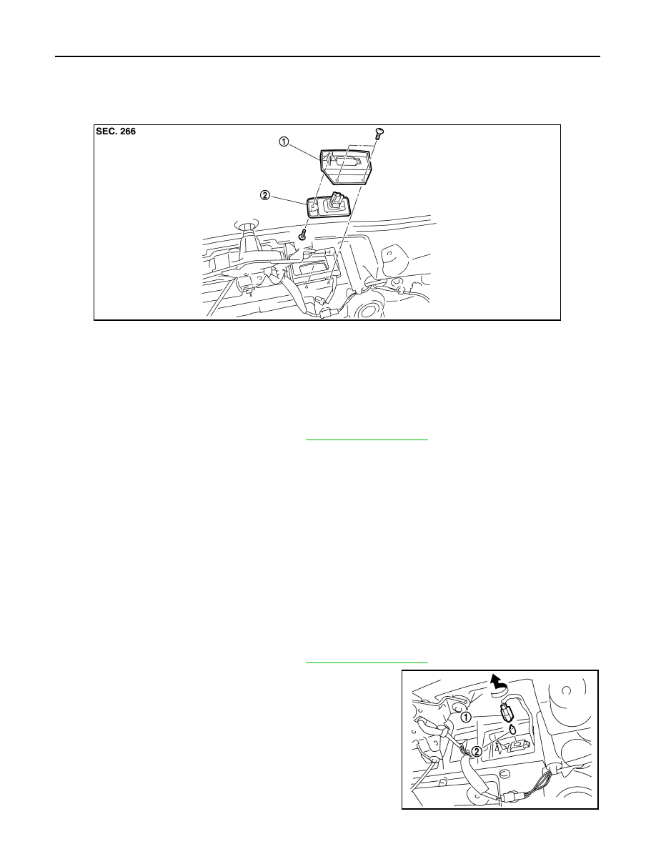
Exploded View
INFOID:0000000009722984
Removal and Installation
INFOID:0000000009722985
CAUTION:
Disconnect the battery negative terminal or remove the fuse.
REMOVAL
1.
Remove the back door finisher inner. Refer to
2.
Remove the screw. And then disconnect the license plate lamp connector.
3.
Remove the license plate lamp.
4.
Remove the screw. And then remove the license plate lamp bracket.
INSTALLATION
Install in the reverse order of removal.
Replacement
INFOID:0000000009722986
CAUTION:
• Disconnect the battery negative terminal or remove the fuse.
• Never touch the glass of bulb directly by hand. Keep grease and other oily matters away from it.
• Never touch bulb by hand while it is lit or right after being turned off.
• Never leave bulb out of lamp reflector for a long time because dust, moisture smoke, etc. may affect
the performance of lamp. When replacing bulb, be sure to replace it with new one.
LICENSE PLATE LAMP BULB
1.
Remove the back door finisher inner. Refer to
2.
Turn the license plate lamp bulb socket (1) counterclockwise
and unlock it.
3.
Remove the bulb (2) from the license plate lamp bulb socket.
1.
License plate lamp bracket
2.
License plate lamp
JPLIA0826ZZ
JPLIA0827ZZ