содержание .. 571 572 573 574 ..
Nissan Murano. Manual - part 573
EC-402
< DTC/CIRCUIT DIAGNOSIS >
[VQ35DE]
P1805 BRAKE SWITCH
Is the inspection result normal?
YES
>> INSPECTION END
NO
>> Replace stop lamp switch. Refer to
.
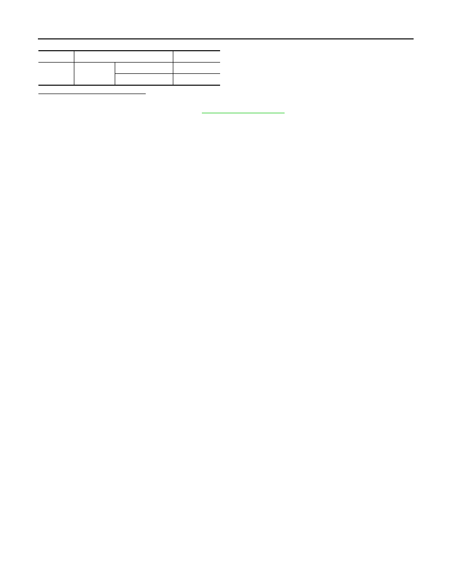
Terminals
Condition
Continuity
1 and 2
Brake pedal
Fully released
Not existed
Slightly depressed
Existed