содержание .. 570 571 572 573 ..
Nissan Murano. Manual - part 572
EC-398
< DTC/CIRCUIT DIAGNOSIS >
[VQ35DE]
P1801 VIAS CONTROL SOLENOID VALVE 2
3.
Check the continuity between VIAS control solenoid valve 2 harness connector and ECM harness con-
nector.
4.
Also check harness for short to ground and short to power.
Is the inspection result normal?
YES
>> GO TO 3.
NO
>> Repair open circuit, short to ground or short to power in harness or connectors.
3.
CHECK VIAS CONTROL SOLENOID VALVE 2
EC-398, "Component Inspection"
Is the inspection result normal?
YES
>> GO TO 4.
NO
>> Replace VIAS control solenoid valve 2. Refer to
.
4.
CHECK INTERMITTENT INCIDENT
GI-44, "Intermittent Incident"
>> INSPECTION END
Component Inspection
INFOID:0000000009720147
1.
CHECK VIAS CONTROL SOLENOID VALVE 2
With CONSULT
1.
Turn ignition switch OFF.
2.
Reconnect all harness connectors disconnected.
3.
Disconnect vacuum hoses connected to VIAS control solenoid valve 2.
4.
Turn ignition switch ON.
5.
Select “VIAS S/V-2” in “ACTIVE TEST” mode with CONSULT.
6.
Check air passage continuity and operation delay time under the
following conditions.
Without CONSULT
1.
Turn ignition switch OFF.
2.
Disconnect VIAS control solenoid valve 2 harness connector.
3.
Disconnect vacuum hoses connected to VIAS volume control solenoid valve 2.
VIAS control solenoid valve 2
ECM
Continuity
Connector
Terminal
Connector
Terminal
F75
2
F7
26
Existed
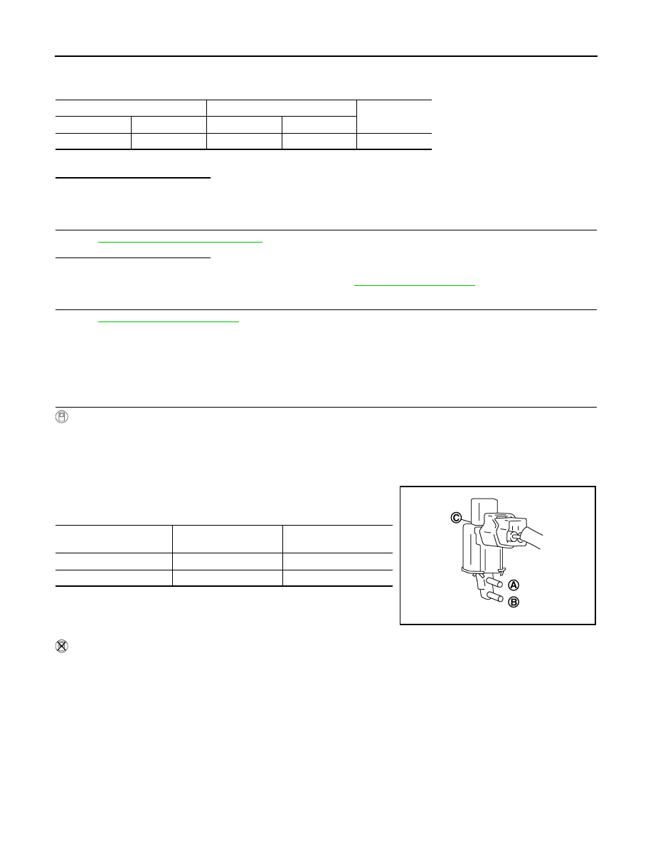
Condition
(VIAS S/V-2)
Air passage continuity
between (A) and (B)
Air passage continuity
between (A) and (C)
ON
Existed
Not existed
OFF
Not existed
Existed
JMBIA0180ZZ