содержание .. 521 522 523 524 ..
Nissan Murano. Manual - part 523
EC-202
< DTC/CIRCUIT DIAGNOSIS >
[VQ35DE]
P0130, P0150 A/F SENSOR 1
3.
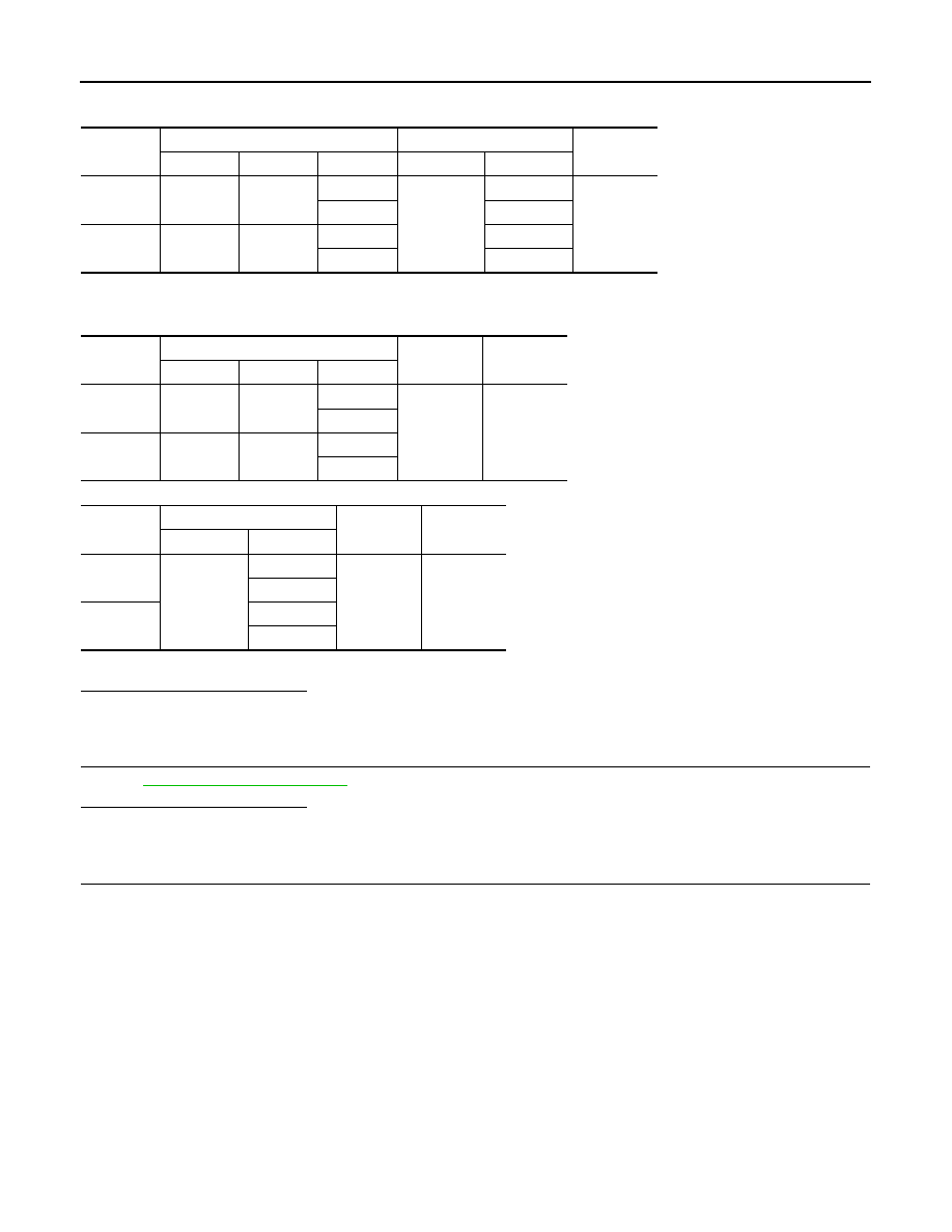
Check the continuity between A/F sensor 1 harness connector and ECM harness connector.
4.
Check the continuity between A/F sensor 1 harness connector and ground, or ECM harness connector
and ground.
5.
Also check harness for short to power.
Is the inspection result normal?
YES
>> GO TO 5.
NO
>> Repair open circuit, short to ground or short to power in harness or connectors.
5.
CHECK INTERMITTENT INCIDENT
Perform
GI-44, "Intermittent Incident"
.
Is the inspection result normal?
YES
>> GO TO 6.
NO
>> Repair or replace malfunctioning part.
6.
REPLACE AIR FUEL RATIO (A/F) SENSOR 1
Replace malfunctioning air fuel ratio (A/F) sensor 1.
CAUTION:
• Discard any A/F sensor which has been dropped from a height of more than 0.5 m (19.7 in) onto a
hard surface such as a concrete floor; use a new one.
• Before installing new A/F sensor, clean exhaust system threads using Oxygen Sensor Thread
Cleaner [commercial service tool (J-43897-18 or J-43897-12)] and approved anti-seize lubricant
(commercial service tool).
>> INSPECTION END
DTC
A/F sensor 1
ECM
Continuity
Bank
Connector
Terminal
Connector
Terminal
P0130
1
F27
1
F8
45
Existed
2
49
P0150
2
F64
1
53
2
57
DTC
A/F sensor 1
Ground
Continuity
Bank
Connector
Terminal
P0130
1
F27
1
Ground
Not existed
2
P0150
2
F64
1
2
DTC
ECM
Ground
Continuity
Connector
Terminal
P0130
F8
45
Ground
Not existed
49
P0150
53
57