содержание .. 169 170 171 172 ..
Nissan Murano. Manual - part 171
AV-462
< REMOVAL AND INSTALLATION >
[BOSE AUDIO WITH NAVIGATION]
MICROPHONE
MICROPHONE
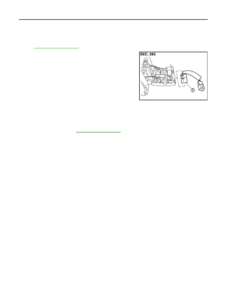
Exploded View
INFOID:0000000009721997
REMOVAL
DISASSEMBLY
Removal and Installation
INFOID:0000000009721998
REMOVAL
1.
Remove map lamp. Refer to
2.
Remove microphone from map lamp.
INSTALLATION
Install in the reverse order of removal.
JSNIA0132ZZ
1.
Microphone