Nissan X-Trail 32. Manual - part 394


  Главная      Nissan     Nissan X-Trail 32 - Service Manual


поиск по сайту            


содержание   ..  392  393  394  395   ..


Nissan X-Trail 32. Manual - part 394


DAS

AROUND VIEW MONITOR CONTROL UNIT

DAS-317

< ECU DIAGNOSIS INFORMATION >

[PARK ASSIST]

C

D

E

F

G

H

I

J

K

L

M

B

N

P

A

Terminal

(Wire color)

Description

Condition

Standard value

Reference value

(Approx.)

+

–

Signal name

Input/

Output

1

(B)

Ground

Ground

—

Ignition 

switch 

ON

—

0 - 0.1 V

0 V

2

(Y)

1

(B)

Battery power supply

Input

Ignition 

switch 

OFF

—

9.5 - 16 V

Battery voltage

4

(SB)

1

(B)

Ignition signal

Input

Ignition 

switch 

ON

—

9.5 - 16 V

Battery voltage

9

(G)

—

Camera switch signal

Input

—

—

—

—

10

(R)

—

CAN-L

Input/

Output

—

—

—

—

12

(L)

—

CAN-H

Input/

Output

—

—

—

—

23

Ground

Camera image signal 
ground

—

Ignition 

switch 

ON

—

0 - 0.1 V

0 V

24

(G)

23

Camera image signal

Output

Ignition 

switch 

ON

—

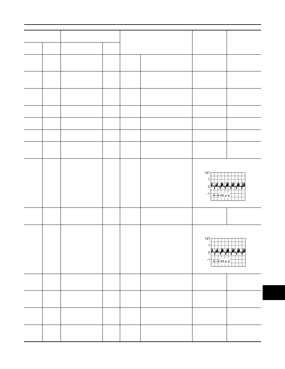
Input the waveform synchronized 

with the camera image signal.

25

(B)

Ground

Rear camera ground

—

Ignition 

switch 

ON

—

0 - 0.1 V

0 V

26

(R)

27

Rear camera image 
signal (+)

Input

Ignition 

switch 

ON

—

Input the waveform synchronized 

with the camera image signal.

27

Ground

Rear camera image 
signal (

−

)

—

Ignition 

switch 

ON

—

0 - 0.1 V

0 V

28

(W)

27

Rear camera power 
supply

Output

Ignition 

switch 

ON

—

5.0 - 9.0 V

6.0 V

29

(Y)

Ground

Driver side camera 
ground

—

Ignition 

switch 

ON

—

0 - 0.1 V

0 V

30

(L)

29

(Y)

Driver side camera 
power supply

Output

Ignition 

switch 

ON

—

5.0 - 9.0 V

6.0 V

JSNIA0834GB

JSNIA0834GB

DAS-318

< ECU DIAGNOSIS INFORMATION >

[PARK ASSIST]

AROUND VIEW MONITOR CONTROL UNIT

With BSW

31

Ground

Driver side camera 
image signal (

−

)

—

Ignition 

switch 

ON

—

0  -  0.1  V

0  V

32

(G)

31

Driver side camera 
image signal (+)

Input

Ignition 

switch 

ON

—

Input the waveform synchronized 

with the camera image signal.

33

(L)

Ground

Passenger side cam-
era ground

—

Ignition 

switch 

ON

—

0  -  0.1  V

0  V

34

(B)

33

(L)

Passenger side cam-
era power supply

Output

Ignition 

switch 

ON

—

5.0 - 9.0 V

6.0 V

35

Ground

Passenger side cam-
era image signal (

−

)

—

Ignition 

switch 

ON

—

0  -  0.1  V

0  V

36

(Y)

35

Passenger side cam-
era image signal (+)

Input

Ignition 

switch 

ON

—

Input the waveform synchronized 

with the camera image signal.

37

(V)

Ground

Front camera ground

—

Ignition 

switch 

ON

—

0  -  0.1  V

0  V

38

(L)

37

(V)

Front camera power 
supply

Output

Ignition 

switch 

ON

—

5.0 - 9.0 V

6.0 V

39

Ground

Front camera image 
signal (

−

)

—

Ignition 

switch 

ON

—

0  -  0.1  V

0  V

40

(LG)

39

Front camera image 
signal (+)

Input

Ignition 

switch 

ON

—

Input the waveform synchronized 

with the camera image signal.

Terminal

(Wire color)

Description

Condition

Standard value

Reference value

(Approx.)

+

–

Signal name

Input/

Output

JSNIA0834GB

JSNIA0834GB

JSNIA0834GB

DAS

AROUND VIEW MONITOR CONTROL UNIT

DAS-319

< ECU DIAGNOSIS INFORMATION >

[PARK ASSIST]

C

D

E

F

G

H

I

J

K

L

M

B

N

P

A

Terminal

(Wire color)

Description

Condition

Standard value

Reference value

(Approx.)

+

–

Signal name

Input/

Output

1

(B)

Ground

Ground

—

Ignition 

switch 

ON

—

0 - 0.1 V

0 V

2

(Y)

1

(B)

Battery power supply

Input

Ignition 

switch 

OFF

—

9.5 - 16 V

Battery voltage

3

(SB)

1

(B)

Ignition signal

Input

Ignition 

switch 

ON

—

9.5 - 16 V

Battery voltage

7

(R)

Ground

BSW indicator LH

Output

Ignition 

switch 

ON

Approx. 2 sec. after ignition 
switch OFF 

⇒

 ON (bulb 

check).

5.5 - 16 V

12.0 V

8

(G)

Ground

BSW indicator RH

Output

Ignition 

switch 

ON

Approx. 2 sec. after ignition 
switch OFF 

⇒

 ON (bulb 

check)

5.5 - 16 V

12.0 V

27

(L)

—

CAN-H

Input/

Output

—

—

—

—

28

(R)

—

CAN-L

Input/

Output

—

—

—

—

36

(Y)

Ground

Communication sig-
nal
(CAMERA 

→

 PUMP)

Output

Ignition 

switch 

ON

—

Input the waveform synchronized 

with the communication status.

37

(V)

Ground

COMM GND

—

Ignition 

switch 

ON

—

0 - 0.1 V

0 V

38

(SB)

Ground

Communication sig-
nal
(PUMP 

→

 CAMERA)

Input

Ignition 

switch 

ON

—

Input the waveform synchronized 

with the communication status.

47

(G)

48

Camera image signal

Output

Ignition 

switch 

ON

—

Input the waveform synchronized 

with the camera image signal.

48

Ground

Camera image signal 
ground

—

Ignition 

switch 

ON

—

0 - 0.1 V

0 V

PKIB5039J

PKIB5039J

JSNIA0834GB

DAS-320

< ECU DIAGNOSIS INFORMATION >

[PARK ASSIST]

AROUND VIEW MONITOR CONTROL UNIT

49

(LG)

52

(B)

Rear camera commu-
nication signal

Input/

Output

Ignition 

switch 

ON

—

Input the waveform synchronized 

with the communication status.

50

(R)

52

(B)

Rear camera power 
supply

Output

Ignition 

switch 

ON

—

5.0 - 9.0 V

6.0 V

52

(B)

Ground

Rear camera ground

—

Ignition 

switch 

ON

—

0  -  0.1  V

0  V

53

(W)

54

Rear camera image 
signal (+)

Input

Ignition 

switch 

ON

—

Input the waveform synchronized 

with the camera image signal.

54

Ground

Rear camera image 
signal (

−

)

—

Ignition 

switch 

ON

—

0  -  0.1  V

0  V

56

(L)

58

(Y)

Driver side camera 
power supply

Output

Ignition 

switch 

ON

—

5.0 - 9.0 V

6.0 V

58

(Y)

Ground

Driver side camera 
ground

—

Ignition 

switch 

ON

—

0  -  0.1  V

0  V

59

(G)

60

Driver side camera 
image signal (+)

Input

Ignition 

switch 

ON

—

Input the waveform synchronized 

with the camera image signal.

60

Ground

Driver side camera 
image signal (

−

)

—

Ignition 

switch 

ON

—

0  -  0.1  V

0  V

62

(B)

64

(L)

Passenger side cam-
era power supply

Output

Ignition 

switch 

ON

—

5.0 - 9.0 V

6.0 V

64

(L)

Ground

Passenger side cam-
era ground

—

Ignition 

switch 

ON

—

0  -  0.1  V

0  V

Terminal

(Wire color)

Description

Condition

Standard value

Reference value

(Approx.)

+

–

Signal name

Input/

Output

JSNIA0836GB

JSNIA0834GB

JSNIA0834GB


содержание   ..  392  393  394  395   ..