Qashqai J11. Transaxle & Transmission - part 32
 

  Index      Nissan     Qashqai J11. Transaxle & Transmission. Service and Repair Manual


Search            copyright infringement  


Content      ..     30      31      32      33     ..


Qashqai J11. Transaxle & Transmission - part 32


TM-498

< BASIC INSPECTION >

[CVT: RE0F10G]

DIAGNOSIS AND REPAIR WORK FLOW

Use 

TM-609, "Symptom Table"

 from the symptom inspection result in step 4. Then identify where to start per-

forming the diagnosis based on possible causes and symptoms.

>> GO TO 8.

7.

REPAIR OR REPLACE THE MALFUNCTIONING PARTS

Repair or replace the detected malfunctioning parts.
Reconnect parts or connector after repairing or replacing, and then erase DTC if necessary.

>> GO TO 8.

8.

FINAL CHECK

Perform “DTC CONFIRMATION PROCEDURE” again to make sure that the repair is correctly performed.
Check that malfunctions are not reproduced when obtaining the malfunction information from the customer,
referring to the symptom inspection result in step 3 or 4.

Is DTC or malfunction symptom reproduced?

YES-1 (DTC is reproduced.)>>GO TO 5.
YES-2 (Malfunction is reproduced.)>>GO TO 6.
NO

>> Before delivering the vehicle to the customer, make sure that DTC is erased.

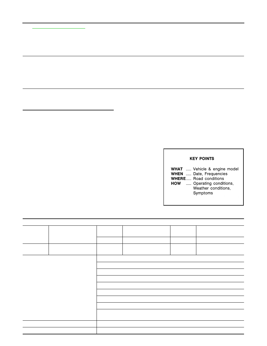
Diagnostic Work Sheet

INFOID:0000000010245571

DESCRIPTION

There are many operating conditions that may cause a malfunction
of the transmission parts. By understanding those conditions prop-
erly, a quick and exact diagnosis can be achieved.
In general, perception of a problem varies depending on individuals.
Ask the customer about his/her concerns carefully. It is important to
understand the phenomenon or status. To systemize all the informa-
tion for the diagnosis, prepare the question sheet referring to the
question points.
In some cases, multiple conditions that appear simultaneously may
cause a DTC to be detected.

Worksheet Sample

SEF907L

Question sheet

Customer's 
name

MR/MS

Registration 
number

Initial year 
registration

Year

Month

day

Vehicle type

Chassis No.

Storage date

Year

Month

day

Engine

Mileage

km/mile

Symptom

†

 Vehicle does not start. (

†

 R position 

†

 D position 

†

 Ds position 

†

 M position)

†

 Upshifting does not occur. 

†

 Downshifting does not occur. 

†

 Lock-up malfunction

†

 Shift point is too high. 

†

 Shift point is too low.

†

 Shift shock (

†

 N

D

†

 Lock-up 

†

 R, D, Ds and M position)

†

 Slip (

†

 N

D

†

 Lock-up 

†

 R, D, Ds and M position)

†

Noise

†

 Vibration

When selector lever position is shifted, shift pattern does not change.

†

 Other

 (

First occurrence

†

 Recently (as from month

 of year

)

Frequency of occurrence

†

 Always 

†

 Under certain conditions 

†

 Sometimes (

 time(s)/day)

DIAGNOSIS AND REPAIR WORK FLOW

TM-499

< BASIC INSPECTION >

[CVT: RE0F10G]

C

E

F

G

H

I

J

K

L

M

A

B

TM

N

O

P

Climate con-
ditions

Irrelevant

Weather

†

 Clear

†

 Cloud

†

 Rain

†

 Snow

†

 Others 

)

Temperature

†

 Hot

†

 Warm

†

 Cool

†

 Cold

†

 Temperature (Approx.

°

C/

°

F)

Relative humidity

†

 High

†

 Moderate

†

 Low

Transaxle condition 

†

 In cold-start 

†

 During warm-up (approx. 

°

C/

°

F)

†

 After warm-up 

†

Engine speed: 

rpm

Road conditions

†

 Urban area

†

 Suburb area

†

 Highway 

†

 Mountainous road (uphill or downhill) 

Operating condition, etc.

Irrelevant

†

 When engine starts

†

 During idling

†

 During driving

†

 During acceleration

†

 At constant speed driving

†

 During deceleration

†

 During cornering (RH curve or LH curve)

Other conditions

Question sheet

Customer's 
name

MR/MS

Registration 
number

Initial year 
registration

Year

Month

day

Vehicle type

Chassis No.

Storage date

Year

Month

day

Engine

Mileage

km/mile

TM-500

< BASIC INSPECTION >

[CVT: RE0F10G]

ADDITIONAL SERVICE WHEN REPLACING TCM

ADDITIONAL SERVICE WHEN REPLACING TCM

Description

INFOID:0000000010245572

Always perform the following items when the TCM is replaced.

TCM PROGRAMMING

• Since vehicle specifications are not yet written in a new TCM, it is necessary to write them with CONSULT.

CAUTION:

When replacing TCM, save TCM data on CONSULT before removing TCM.

SAVING AND WRITING OF TCM DATA

• TCM performs accurate control by retrieving data (inherent characteristic value) of each solenoid. For this

reason, it is necessary to save data of current TCM in CONSULT before replacing the TCM. After this, the
saved data must be written in new TCM.

CALIBRATION OF G SENSOR

• TCM stores calibration data (inherent characteristic value) of G sensor to provide accurate control. There-

fore, it is required to perform calibration of G sensor after the replacement of TCM.

BLEEDING OF ELECTRIC OIL PUMP

• If TCM is replaced, air bleeding of the electric oil pump memorized in TCM is reset. The data monitor dis-

plays “INCOMP”. It is necessary to bleed air to “COMP” the value.

Work Procedure

INFOID:0000000010245573

1.

SAVE TCM DATA (IP CHARACTERISTICS VALUE)

NOTE:
Save necessary data stored in TCM in CONSULT according to the following instructions:

With CONSULT

1.

Turn ignition switch OFF and wait for 10 seconds.

2.

Turn ignition switch ON.

3.

Select “Work Support” in “TRANSMISSION”.

4.

Select “READ IP CHARA - REPLACEMENT TCM”.

5.

Import data according to the instructions on the CONSULT screen.

>> GO TO 2.

2.

SAVING TCM DATA (VEHICLE SPECIFICATIONS)

With CONSULT

1.

Turn ignition switch OFF.

2.

Turn ignition switch ON.

3.

Select “Re/programming, Configuration”.

4.

Select “AT/CVT”.
NOTE:
If “AT/CVT” is not displayed and TCM data cannot be saved on CONSULT, GO TO 3.

5.

Select “Programming”.

6.

Save TCM data on CONSULT according to the CONSULT display.

>> GO TO 3.

3.

REPLACE TCM

1.

Turn ignition switch OFF and wait for 10 seconds.

2.

Replace the TCM. Refer to 

TM-625, "Removal and Installation"

.

>> GO TO 4.

4.

WRITE TCM DATA (VEHICLE SPECIFICATIONS)

With CONSULT

1.

Select “Programming”.

ADDITIONAL SERVICE WHEN REPLACING TCM

TM-501

< BASIC INSPECTION >

[CVT: RE0F10G]

C

E

F

G

H

I

J

K

L

M

A

B

TM

N

O

P

2.

Perform programming according to the CONSULT display.

>> GO TO 5.

5.

WRITE TCM DATA (IP CHARACTERISTICS VALUE)

NOTE:
Write data saved in CONSULT into a new TCM according to the following instructions:

With CONSULT

1.

Turn ignition switch OFF and wait for 10 seconds.

2.

Turn ignition switch ON.

3.

Select “Work Support” in “TRANSMISSION”.

4.

Select “WRITE IP CHARA - REPLACEMENT TCM”.

5.

Write data saved in CONSULT in TCM according to the instructions on the CONSULT screen.

>> GO TO 6.

6.

CALIBRATE G SENSOR 

Refer to 

TM-506, "Work Procedure"

.

>> GO TO 7.

7.

BLEED ELECTRIC OIL PUMP

Refer to 

TM-507, "Work Procedure"

.

>> WORK END

TM-502

< BASIC INSPECTION >

[CVT: RE0F10G]

ADDITIONAL SERVICE WHEN REPLACING TRANSAXLE ASSEMBLY

ADDITIONAL SERVICE WHEN REPLACING TRANSAXLE ASSEMBLY

Description

INFOID:0000000010245574

Perform the following work after the transaxle assembly is replaced.

ERASING AND WRITING TCM DATA

• TCM performs accurate control by retrieving data (inherent characteristic value) of each solenoid. For this

reason, after replacing transaxle assembly, it is necessary to erase data stored in TCM and write new data.

ERASING OF CVT FLUID DEGRADATION LEVEL DATA 

• TCM records the degradation level of the CVT fluid calculated from the vehicle driving status. Therefore, if

the transaxle assembly is replaced, it is necessary to erase the CVT fluid degradation level data recorded by
TCM. 

BLEEDING OF ELECTRIC OIL PUMP

• The electric oil pump suctions oil from the oil pan through the sub-strainer. If air is contained in the sub-

strainer, oil pressure cannot be generated and it is necessary to bleed air.

Work Procedure

INFOID:0000000010245575

1.

CHECK THE SERIAL NUMBER (PART 1)

Write down the serial number of new transaxle assembly.

>> GO TO 2.

2.

WRITE TCM DATA (IP CHARACTERISTICS VALUE)

NOTE:
Write data of new solenoid in TCM according to the following instructions:

With CONSULT

CAUTION:

When the work is interrupted, obtain data again from the supplied CD.
1.

Shift the selector lever to the P position.

2.

Turn ignition switch OFF and wait for 10 seconds.

3.

Turn ignition switch ON.

4.

Insert the supplied CD into CONSULT. Refer to CONSULT operation manual.

5.

Select “Work Support” in “TRANSMISSION”.

6.

Select “WRITE IP CHARA - REPLACEMENT AT/CVT”.

7.

Check that the serial number displayed on CONSULT screen and those written in the memo agree.

8.

Write data in TCM according to the instructions on the CONSULT screen.
NOTE:
When writing is complete, the shift position indicator of the combination meter displays P.

JSDIA4208GB

ADDITIONAL SERVICE WHEN REPLACING TRANSAXLE ASSEMBLY

TM-503

< BASIC INSPECTION >

[CVT: RE0F10G]

C

E

F

G

H

I

J

K

L

M

A

B

TM

N

O

P

>> GO TO 3.

3.

ERASE CVT FLUID DEGRADATION LEVEL DATA

With CONSULT

1.

Select “WORK SUPPORT” in “TRANSMISSION”.

2.

Select “CONFORM CVTF DETERIORTN”.

3.

Touch “Clear”.

>> GO TO 4.

4.

BLEED ELECTRIC OIL PUMP

Refer to 

TM-507, "Work Procedure"

.

>> WORK END

TM-504

< BASIC INSPECTION >

[CVT: RE0F10G]

ADDITIONAL SERVICE WHEN REPLACING TCM AND TRANSAXLE ASSEM-

BLY

ADDITIONAL SERVICE WHEN REPLACING TCM AND TRANSAXLE AS-
SEMBLY

Description

INFOID:0000000010499205

When replacing TCM and transaxle assembly as a set, perform the following work.

TCM PROGRAMMING

• Since vehicle specifications are not yet written in a new TCM, it is necessary to write them with CONSULT.

CAUTION:

When replacing TCM, save TCM data on CONSULT before removing TCM.

WRITING TCM DATA

• TCM performs accurate control by retrieving data (inherent characteristic value) of each solenoid. For this

reason, after replacing TCM and transaxle assembly, it is necessary to write new data in TCM.

CALIBRATION OF G SENSOR

• TCM stores calibration data (inherent characteristic value) of G sensor to provide accurate control. There-

fore, it is required to perform calibration of G sensor after the replacement of TCM.

BLEEDING OF ELECTRIC OIL PUMP

• The electric oil pump suctions oil from the oil pan through the sub-strainer. If air is contained in the sub-

strainer, oil pressure cannot be generated and it is necessary to bleed air.

Work Procedure

INFOID:0000000010499206

1.

SAVE TCM DATA (VEHICLE SPECIFICATIONS)

With CONSULT

1.

Turn ignition switch OFF.

2.

Turn ignition switch ON.

3.

Select “Re/programming, Configuration”.

4.

Select “AT/CVT”.
NOTE:
If “AT/CVT” is not displayed and TCM data cannot be saved on CONSULT, GO TO 2.

5.

Select “Programming”.

6.

Save TCM data on CONSULT according to the CONSULT display.

>> GO TO 2.

2.

REPLACE TCM AND TRANSAXLE ASSEMBLY

Replace TCM and transaxle assembly. Refer to 

TM-625, "Removal and Installation"

 (TCM), 

TM-653,

"Removal and Installation"

 (Transaxle assembly).

CAUTION:

ADDITIONAL SERVICE WHEN REPLACING TCM AND TRANSAXLE ASSEM-

BLY

TM-505

< BASIC INSPECTION >

[CVT: RE0F10G]

C

E

F

G

H

I

J

K

L

M

A

B

TM

N

O

P

Write down the serial number of new transaxle assembly.

>> GO TO 3.

3.

WRITE TCM DATA (VEHICLE SPECIFICATIONS)

NOTE:
Write data of vehicle specifications in TCM according to the following instructions:

With CONSULT

1.

Select “Programming”.

2.

Perform programming according to the CONSULT display.

>> GO TO 4.

4.

WRITE TCM DATA (IP CHARACTERISTICS VALUE)

NOTE:
Write data of new solenoid in TCM according to the following instructions:

With CONSULT

1.

Turn ignition switch ON.

2.

Insert the supplied CD into CONSULT. Refer to CONSULT operation manual.

3.

Select “Work Support” in “TRANSMISSION”.

4.

Select “WRITE IP CHARA - REPLACEMENT AT/CVT”.

5.

Check that the serial number displayed on CONSULT screen and those written in the memo agree.

6.

Write data in TCM according to the instructions on the CONSULT screen.
NOTE:
When writing is complete, the shift position indicator of the combination meter displays P.

>> GO TO 5.

5.

CALIBRATE G SENSOR 

Refer to 

TM-506, "Work Procedure"

.

>> GO TO 6.

6.

BLEED ELECTRIC OIL PUMP

Refer to 

TM-507, "Work Procedure"

.

>> WORK END

JSDIA4208GB

TM-506

< BASIC INSPECTION >

[CVT: RE0F10G]

CALIBRATION OF G SENSOR

CALIBRATION OF G SENSOR

Description

INFOID:0000000010327504

TCM stores calibration data (inherent characteristic value) of G sensor to provide accurate control. Therefore,
it is required to perform calibration of G sensor after the following work is performed.
• Removal/installation or replacement of G sensor 
• Replacement of TCM

Work Procedure

INFOID:0000000010327505

1.

PREPARATION BEFORE CALIBRATION PROCEDURE

1.

Park the vehicle on a level surface.

2.

Adjust air pressure of all tires to the specified pressure. Refer to 

WT-66, "Tire Air Pressure"

>> GO TO 2.

2.

CALIBRATE G SENSOR

With CONSULT

1.

Turn ignition switch ON.

CAUTION:

Never start engine.

2.

Select “Work Support” in “TRANSMISSION”.

3.

Select “G SENSOR CALIBRATION”.

4.

Touch “Start”.

CAUTION:

Never swing the vehicle during “G sensor calibration”. 

Is “COMPLETED” displayed? 

YES

>> GO TO 3.

NO

>> Perform steps 1 and 2 again.

3.

CHECK DTC

With CONSULT

1.

Turn ignition switch OFF and wait for 10 seconds. 

2.

Turn ignition switch ON.

3.

Select “Self Diagnostic Results” in “TRANSMISSION”.

Is “P1586” or “P1588” detected? 

YES

>> Go to 

TM-485, "DTC Index"

.

NO

>> Calibration end

BLEEDING ELECTRIC OIL PUMP

TM-507

< BASIC INSPECTION >

[CVT: RE0F10G]

C

E

F

G

H

I

J

K

L

M

A

B

TM

N

O

P

BLEEDING ELECTRIC OIL PUMP

Description

INFOID:0000000010326094

The electric oil pump suctions oil from the oil pan through the sub-strainer. If air is contained in the sub-
strainer, oil pressure cannot be generated and it is necessary to bleed air.    

Work Procedure

INFOID:0000000010326095

1.

PREPARATION BEFORE WORK

1.

Start the engine and warm it up.

2.

After warm-up, stop the engine and wait for 60 seconds or more.

>> GO TO 2.

2.

BLEED ELECTRIC OIL PUMP

With CONSULT

1.

Turn ignition switch ON.

CAUTION:

Never start the engine.

2.

Shift the selector lever to the P position.

3.

Select “WORK SUPPORT” in “TRANSMISSION”.

4.

Select “ELECTRIC O.P. AIR BLEEDING”. 

5.

Touch “Start”.

CAUTION:

Never start the engine during air bleeding. 
NOTE:
It may take approximately 20 seconds until completion. 

Is “COMPLETED” displayed?

YES

>> GO TO 3.

NO

>> Turn OFF the ignition switch and wait for 10 seconds or more. Then, start the work again. 

3.

CHECK THE COMPLETION OF BLEEDING ELECTRIC OIL PUMP (PART 1)

With CONSULT

1.

Start the engine.

2.

Wait for 10 seconds. 

3.

Turn ignition switch OFF.

4.

Wait for 10 seconds. 

5.

Turn ignition switch ON.

CAUTION:

Never start the engine.

6.

Select “Data Monitor” in “TRANSMISSION”.

7.

Select “AIR BLDING STATE”. 

Is “COMP” displayed?

YES

>> GO TO 4.

NO

>> Turn OFF the ignition switch and wait for 10 seconds or more. Then, start the work again. 

4.

CHECK THE COMPLETION OF BLEEDING ELECTRIC OIL PUMP (PART 2)

1.

Start the engine.

2.

Activate stop/start system. Refer to 

EC9-39, "STOP/START SYSTEM : System Description (M/T mod-

els)"

.

Does the stop/start system start?

YES

>> WORK END

NO

>> Check DTC “P188F”. Refer to 

TM-588, "DTC Logic"

.

TM-508

< BASIC INSPECTION >

[CVT: RE0F10G]

STALL TEST

STALL TEST

Work Procedure

INFOID:0000000010245576

INSPECTION

1.

Check the engine oil level. Replenish if necessary. Refer to 

LU-48, "Inspection"

.

2.

Check for leak of the CVT fluid. Refer to 

TM-613, "Inspection"

.

3.

Drive for about 10 minutes to warm up the vehicle so that the CVT fluid temperature is 50 to 80

°

C (122 to

176

°

F).

4.

Be sure to apply the parking brake and block the tires. 

5.

Start the engine, depress the brake pedal and put the selector lever to the D position. 

6.

While depressing the brake pedal, depress the accelerator pedal gradually. 

7.

Read the stall speed quickly. Then, release your foot from the accelerator pedal quickly. 

CAUTION:

Do not depress the accelerator pedal for 5 seconds or more during the test. 

8.

Place the selector lever in the N position.

9.

Cool the CVT fluid. 

CAUTION:

Run the engine with the idle speed for at least 1 minute. 

10. Put the selector lever to the R position and perform Step 6 to Step 9 again. 

NARROWING-DOWN MALFUNCTIONING PARTS

O: Within the stall speed standard value.

H: Stall speed is higher than the standard value. 

L: Stall speed is lower than the standard value. 

Stall speed

: Refer to 

TM-659, "Stall Speed"

.

Selector lever position

Possible cause

D

R

Stall speed

H

O

• Forward  clutch

O

H

• Reverse brake 

L

L

• Engine
• Torque converter one way clutch 

H

H

• Line pressure is low. 
• Primary pulley 
• Secondary pulley
• Steel belt

CVT POSITION

TM-509

< BASIC INSPECTION >

[CVT: RE0F10G]

C

E

F

G

H

I

J

K

L

M

A

B

TM

N

O

P

CVT POSITION

Inspection

INFOID:0000000010245577

1.

Turn ON the ignition switch with the shift selector at the “P” position. 

2.

Press the shift selector button with the brake pedal depressed, and confirm that the shift selector can be
moved to positions other than “P”. Also confirm that movement is not allowed from the “P” position to other
position without depressing the brake pedal. 

3.

Move the shift selector and check for “excessive effort”, “sticking”, “noise” or “rattle”.

4.

Confirm that shift selector stops at each position with the feel of engagement when it is moved through all
the positions. Check whether or not the actual position the shift selector is in matches the position shown
by the transaxle body.

5.

Make sure that the shift selector is moved to all the shift posi-
tions in the manner shown.

6.

When the shift selector button is pressed without applying for-
ward/backward force to the shift selector at “P”, “R”, “N”, “D”
positions, there should be no “sticking” on the shift selector but-
ton operation. 

7.

The relationship between selector lever, engine starting ability,
and shift position indicator lighting should satisfy the conditions
of the following table.

8.

Confirm that the back-up lamps illuminate only when lever is placed in the “R” position. Confirm that the
back-up lamps does not illuminate when selector lever is pushed against “R” position in the “P” or “N”
position.

9.

Check that the transaxle is locked when the selector lever is in the “P” position.

10. When selector lever is set to manual shift gate, make sure that manual mode is displayed on combination

meter.
Shift selector lever to “+” and “

” sides, and check that set shift position changes.

Adjustment

INFOID:0000000010245578

1.

Shift the selector lever to the “P” position.

CAUTION:

Rotate the wheels at least a quarter turn and be certain the Park position mechanism is fully
engaged.

2.

Loosen nut 

 and set manual lever 

 to the “P” position. 

CAUTION:

Never apply force to the manual lever. 

3.

Hold the control cable 

 and push it to direction of the arrow

with a specified force.

4.

Temporarily tighten the nut with the control cable loose.

5.

Tighten the nut to the specified torque. Refer to 

TM-620,

"Exploded View"

.

CAUTION:

In tightening, fix the manual lever. 

JPDIA0344GB

Selector lever 

position

Load direction to the se-

lector lever

Applied load to the se-

lector lever

Engine starting ability

Shift position indicator lighting

P

P (over stroke) 

 P 

 R

30 N (3.1 kg, 6.7 lb)

Start

P indicator shall be illuminated

R

 R

Not start

R indicator shall be illuminated

N

 N

Start

N indicator shall be illuminated

D

Not  start

Specified force

: 9.8 N (1.0 kg, 2.2 lb)

JSDIA4171ZZ

TM-510

< DTC/CIRCUIT DIAGNOSIS >

[CVT: RE0F10G]

U0073 COMMUNICATION BUS A OFF

DTC/CIRCUIT DIAGNOSIS

U0073 COMMUNICATION BUS A OFF

DTC Logic

INFOID:0000000010245579

DTC DETECTION LOGIC

DTC CONFIRMATION PROCEDURE

1.

PREPARATION BEFORE WORK

If another “DTC CONFIRMATION PROCEDURE” occurs just before, turn ignition switch OFF and wait for at
least 10 seconds, then perform the next test.

>> GO TO 2.

2.

PERFORM DTC CONFIRMATION PROCEDURE

1.

Start the engine and wait for at least 5 seconds.

2.

Check the DTC.

Is “U0073” detected?

YES

>> Go to 

TM-510, "Diagnosis Procedure"

.

NO

>> INSPECTION END

Diagnosis Procedure

INFOID:0000000010245580

For the diagnosis procedure, refer to 

LAN-24, "Trouble Diagnosis Flow Chart"

DTC

CONSULT screen terms

(Trouble diagnosis content)

DTC detection condition

Possible causes

U0073

COMM BUS A OFF
(Control Module Communica-
tion Bus A Off)

TCM communication blockage lasts for 2 sec-
onds or more when turning ON the ignition 
switch. (Communication not established.)

Harness or connector
(CAN communication line is error)

U0100 LOST COMMUNICATION (ECM A)

TM-511

< DTC/CIRCUIT DIAGNOSIS >

[CVT: RE0F10G]

C

E

F

G

H

I

J

K

L

M

A

B

TM

N

O

P

U0100 LOST COMMUNICATION (ECM A)

DTC Logic

INFOID:0000000010245581

DTC DETECTION LOGIC

DTC CONFIRMATION PROCEDURE

1.

PREPARATION BEFORE WORK

If another “DTC CONFIRMATION PROCEDURE” occurs just before, turn ignition switch OFF and wait for at
least 10 seconds, then perform the next test.

>> GO TO 2.

2.

PERFORM DTC CONFIRMATION PROCEDURE

1.

Start the engine and wait for at least 5 seconds.

2.

Check the DTC.

Is “U0100” detected?

YES

>> Go to 

TM-511, "Diagnosis Procedure"

.

NO

>> INSPECTION END

Diagnosis Procedure

INFOID:0000000010245582

For the diagnosis procedure, refer to 

LAN-24, "Trouble Diagnosis Flow Chart"

DTC

CONSULT screen terms

(Trouble diagnosis content)

DTC detection condition

Possible causes

U0100

LOST COMM (ECM A)
(Lost Communication With 
ECM/PCM A)

When the ignition switch is ON, TCM is un-
able to receive the CAN communications 
signal from ECM continuously for 2 sec-
onds or more.

• ECM
• Harness or connector

(CAN communication line is open or 
shorted)

TM-512

< DTC/CIRCUIT DIAGNOSIS >

[CVT: RE0F10G]

U0140 LOST COMMUNICATION (BCM)

U0140 LOST COMMUNICATION (BCM)

DTC Logic

INFOID:0000000010245583

DTC DETECTION LOGIC

DTC CONFIRMATION PROCEDURE

1.

PREPARATION BEFORE WORK

If another “DTC CONFIRMATION PROCEDURE” occurs just before, turn ignition switch OFF and wait for at
least 10 seconds, then perform the next test.

>> GO TO 2.

2.

PERFORM DTC CONFIRMATION PROCEDURE

With CONSULT

1.

Start the engine and wait for at least 5 seconds.

2.

Check the DTC.

Is “U0140” detected?

YES

>> Go to 

TM-512, "Diagnosis Procedure"

.

NO

>> INSPECTION END

Diagnosis Procedure

INFOID:0000000010245584

For the diagnosis procedure, refer to 

LAN-24, "Trouble Diagnosis Flow Chart"

DTC

CONSULT screen terms

(Trouble diagnosis content)

DTC detection condition

Possible causes

U0140

LOST COMM (BCM)
(Lost Communication With 
Body Control Module)

When the ignition switch is ON, TCM is unable 
to receive the CAN communications signal 
from BCM continuously for 2 seconds or more.

• BCM
• Harness or connector

(CAN communication line is open or 
shorted)

U0141 LOST COMMUNICATION (BCM A)

TM-513

< DTC/CIRCUIT DIAGNOSIS >

[CVT: RE0F10G]

C

E

F

G

H

I

J

K

L

M

A

B

TM

N

O

P

U0141 LOST COMMUNICATION (BCM A)

DTC Logic

INFOID:0000000010245585

DTC DETECTION LOGIC

DTC CONFIRMATION PROCEDURE

1.

PREPARATION BEFORE WORK

If another “DTC CONFIRMATION PROCEDURE” occurs just before, turn ignition switch OFF and wait for at
least 10 seconds, then perform the next test.

>> GO TO 2.

2.

PERFORM DTC CONFIRMATION PROCEDURE

With CONSULT

1.

Start the engine and wait for at least 5 seconds.

2.

Check the DTC.

Is “U0141” detected?

YES

>> Go to 

TM-513, "Diagnosis Procedure"

.

NO

>> INSPECTION END

Diagnosis Procedure

INFOID:0000000010245586

For the diagnosis procedure, refer to 

LAN-24, "Trouble Diagnosis Flow Chart"

DTC

CONSULT screen terms

(Trouble diagnosis content)

DTC detection condition

Possible causes

U0141

LOST COMM (BCM A)
(Lost Communication With 
Body Control Module A)

When the ignition switch is turned ON, TCM 
continues no reception of the CAN communi-
cation signal from IPDM E/R for 2 seconds or 
more. 

• IPDM E/R
• Harness or connector

(CAN communication line is open or 
shorted)


Content      ..     30      31      32      33     ..