Qashqai J11. Transaxle & Transmission - part 6


  Index      Nissan     Qashqai J11. Transaxle & Transmission. Service and Repair Manual


Search            copyright infringement  


Content      ..     4      5      6      7     ..


Qashqai J11. Transaxle & Transmission - part 6


TM-82

< REMOVAL AND INSTALLATION >

[6MT: RS6F95R]

DIFFERENTIAL OUTPUT SEAL

REMOVAL AND INSTALLATION

DIFFERENTIAL OUTPUT SEAL

Exploded View

INFOID:0000000010428775

Refer to 

TM-91, "Exploded View"

.

Removal and Installation

INFOID:0000000010428776

REMOVAL

1.

Remove front drive shafts. Refer to 

FAX-22, "Removal and Installation (LH)"

 or 

FAX-26, "Removal and

Installation (RH)"

.

2.

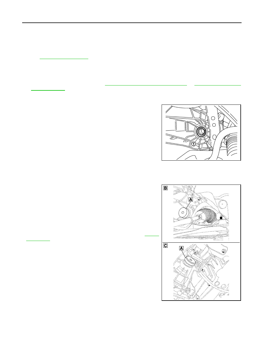
Tap the base of the differential output seal using a roll pin punch and a small hammer to rotate it in its
housing.

3.

Remove differential output seals (1) using pliers, taking care not
to damage the splines.

CAUTION:

Never damage transaxle case and clutch housing.

INSTALLATION

Note the following, and install in the reverse order of removal.

CAUTION:

Lubricate differential output seals before installing
• Install differential output seals (1) to clutch housing and transaxle

case using the drift (A) [SST: Bvi. 1689].

CAUTION:

• Never reuse differential side oil seal.
• When installing, never incline differential output seals.
• Never damage clutch housing and transaxle case.

•  Check oil level and oil leakage after installation. Refer to 

TM-81,

"Inspection"

.

SCIA7625E

B

: Transaxle case side

C

: Clutch housing side

E1DIA0341ZZ

CONTROL LINKAGE

TM-83

< REMOVAL AND INSTALLATION >

[6MT: RS6F95R]

C

E

F

G

H

I

J

K

L

M

A

B

TM

N

O

P

CONTROL LINKAGE

Exploded View

INFOID:0000000010428777

Removal and Installation

INFOID:0000000010428778

REMOVAL 

1.

Remove the air cleaner case and air duct (inlet) or air ducts. Refer to 

EM-380, "Removal and Installation"

.

2.

Remove the battery. Refer to 

PG-155, "Removal and Installation"

.

1.

Bracket

2.

Shift cable

3.

Selector lever

4.

Shifter lever

5.

Tapping bolt

6.

Cable mounting bracket

7.

Select cable

8.

Grommet

9.

Control device assembly

10. Control lever

11.

Control lever knob

Refer to 

GI-4, "Components"

 for the symbols in the figure.

JPDIC0058GB

TM-84

< REMOVAL AND INSTALLATION >

[6MT: RS6F95R]

CONTROL LINKAGE

3.

While pressing the lock of the select cable in the direction of the
arrow shown in the figure, remove the select cable from the
selector lever.

4.

While pressing the lock of the shift cable in the direction of the
arrow shown in the figure, remove the shift cable from the shifter
lever.

5.

While pulling the lock of the select cable in the direction of the
arrow shown in the figure, remove the select cable from the
cable mounting bracket.

6.

While pulling the lock of the shift cable in the direction of the
arrow shown in the figure, remove the shift cable from the cable
mounting bracket.

7.

Remove the control lever knob:
• Push the lever knob ornament to the top, then remove it,
• Turn the control lever knob to the left, then remove it.

8.

Remove console finisher assembly and the center console assembly. Refer to 

IP-19, "Removal and Instal-

lation"

.

9.

Shift the control lever to the neutral position.

10. While pressing the lock of the select cable in the direction of the

arrow shown in the figure, remove the select cable from the con-
trol device assembly.

11. While pressing the lock of the shift cable in the direction of the

arrow shown in the figure, remove the shift cable from the con-
trol device assembly.

12. While pulling the lock of the select cable in the direction of the

arrow shown in the figure, remove the select cable from the con-
trol device assembly.

13. While pulling the lock of the shift cable in the direction of the

arrow shown in the figure, remove the shift cable from the con-
trol device assembly.

14. Remove the control device assembly.
15. Remove the heat plate.

16. Remove the bracket.

17. Remove the grommet and then remove the shift cable and

select cable from the vehicle.

INSTALLATION

Note the following, and install in the reverse order of removal.
• Shift the control lever to the neutral position.

JPDIC0066ZZ

JPDIC0067ZZ

JPDIC0066ZZ

JPDIC0067ZZ

CONTROL LINKAGE

TM-85

< REMOVAL AND INSTALLATION >

[6MT: RS6F95R]

C

E

F

G

H

I

J

K

L

M

A

B

TM

N

O

P

• Securely assemble each cable and the selector lever and shifter lever.
• Securely assemble each cable and the cable mounting bracket.
• Securely assemble each cable and the control device assembly.
• Make sure that the claws of grommet are in contact with the floor.
• Be careful about the installation direction and push the control lever knob into the control lever.

CAUTION:

Never reuse control lever knob.

• Tapping work for tapping bolt is not applied to new clutch housing. Do not perform tapping by other than

screwing tapping bolt because tapping is formed by screwing tapping bolt into clutch housing.

CAUTION:

Never reuse tapping bolt.

Install the select cable (the control device assembly side) with the following procedure.

1.

While pulling the lock of the select cable in the direction of the
arrow shown in the figure, install the select cable to the control
device assembly.

2.

Slide the lock (1) of the select cable in the direction of the arrow
as shown in the figure to pull up the stopper (2) of the select
cable.

3.

Install the end of the select cable to the pin of the control device
assembly.

4.

Install the lever stopper pin (1) or a pin [3 mm (0.12 in) dia.] to
the control device assembly.

CAUTION:

Select cable cannot be adjusted accurately without a use of
a lever stopper pin or a pin [3 mm (0.12 in) dia.].
NOTE:
A lever stopper pin is not included in control device assembly.
Therefore, if the control device assembly is not replaced, pre-
pare a pin [3 mm (0.12 in) dia.].

5.

Check that the control lever does not move in the direction of the
select. If it moves, repeat step 3.

6.

Shift the control lever to 4th gear position.

7.

With the stopper (1) of the select cable pressed into all the way,
slide lock (2) of the select cable all the way in the direction of the
arrow.

8.

Remove the lever stopper pin or a pin [3 mm (0.12 in) dia.] from
the control device assembly.

9.

Shift the control lever to each gear position to check that there is
no bindings. If any, repeat step 3.

JPDIC0067ZZ

JPDIC0064ZZ

JPDIC0069ZZ

JPDIC0065ZZ

TM-86

< REMOVAL AND INSTALLATION >

[6MT: RS6F95R]

CONTROL LINKAGE

Inspection

INFOID:0000000010428779

After installing, confirm the following items:
• When the control lever is shifted to 1st-2nd side and 5th-6th side, confirm the control lever returns to neutral

position smoothly.

• When the control lever is shifted to each position, make sure there is no binding or disconnection in each

boot.

AIR BREATHER HOSE

TM-87

< REMOVAL AND INSTALLATION >

[6MT: RS6F95R]

C

E

F

G

H

I

J

K

L

M

A

B

TM

N

O

P

AIR BREATHER HOSE

Exploded View

INFOID:0000000010428780

Removal and Installation

INFOID:0000000010428781

REMOVAL

Refer to the figure for removal procedure.

INSTALLATION

Refer to the figure for installation procedure.
• The hook of the clamp shall face frontward direction of the vehicle.

1.

Transaxle assembly

2.

Air breather hose

3.

Clamp

4.

Connecting tube

: Vehicle front

E1DIA0337ZZ

TM-88

< UNIT REMOVAL AND INSTALLATION >

[6MT: RS6F95R]

TRANSAXLE ASSEMBLY

UNIT REMOVAL AND INSTALLATION

TRANSAXLE ASSEMBLY

Exploded View

INFOID:0000000010428782

CAUTION:

If transaxle assembly is removed from the vehicle, always replace CSC (Concentric Slave Cylinder). Return CSC insert to orig-
inal position to remove transaxle assembly. Dust on clutch disc sliding parts may damage seal of CSC and may cause clutch
fluid leakage.

Removal and Installation

INFOID:0000000010428783

CAUTION:

If transaxle assembly is removed from the vehicle, always replace CSC (Concentric Slave Cylinder).
Return CSC insert to original position to remove transaxle assembly. Dust on clutch disc sliding parts
may damage seal of CSC and may cause clutch fluid leakage.

REMOVAL

1.

Disconnect the battery cable from the negative terminal.

2.

Remove air cleaner case and air duct (inlet). Refer to 

EM-380, "Removal and Installation"

 .

3.

Remove battery. Refer to 

PG-155, "Removal and Installation"

.

4.

Remove battery bracket .

5.

Drain clutch fluid and then remove clutch tube from CSC (Concentric Slave Cylinder). Refer to 

CL-17,

"Removal and Installation"

.

CAUTION:

Never depress clutch pedal during removal procedure.

6.

Disconnect position switch harness connector.

7.

Disconnect ground cable.

8.

Remove wire harnesses from transaxle assembly.

9.

Disconnect select cable and shift cable from transaxle assembly. Refer to 

TM-83, "Removal and Installa-

tion"

.

10. Remove starter motor. Refer to 

STR-32, "R9M : Removal and Installation"

.

11. Remove engine under cover.

12. Cap or plug transmission assembly opening(s) to prevent fluid from spilling.

E1DIA0339ZZ

1.

Transaxle assembly

A: For the tightening torque, refer to “INSTALLATION”.

TRANSAXLE ASSEMBLY

TM-89

< UNIT REMOVAL AND INSTALLATION >

[6MT: RS6F95R]

C

E

F

G

H

I

J

K

L

M

A

B

TM

N

O

P

13. Remove exhaust front tube. Refer to 

EX-22, "Removal and Installation"

 .

14. Remove front drive shafts. Refer to 

FAX-22, "Removal and Installation (LH)"

  or 

FAX-26, "Removal and

Installation (RH)"

 .

NOTE:
Insert a suitable plug into differential side oil seal after removing front drive shaft.

15. Remove rear engine mounting brackets and rear torque rod.  Refer to 

EM-431, "Removal and Installa-

tion"

.

16. Remove suspension member and suspension member stay. Refer to 

EM-431, "Removal and Installation"

.

17. Set a suitable jack to transaxle assembly and then set a suitable jack to engine assembly.

CAUTION:

When setting a suitable jack, be careful so that it does not contact with the switch.

18. Remove transaxle assembly mounting bolts.

19. Remove engine mounting through bolt-securing nut. Refer to 

EM-431, "Removal and Installation"

 .

20. Remove transaxle assembly from the vehicle.

CAUTION:

• Secure transaxle assembly to a suitable jack while removing it.
• The transaxle assembly must not interfere with the wire harnesses and clutch tube.

21. Remove CSC (Concentric Slave Cylinder). Refer to 

CL-17, "Removal and Installation"

.

CAUTION:

If transaxle assembly is removed from the vehicle, always replace CSC (Concentric Slave Cylin-
der). Return CSC insert to original position to remove transaxle assembly. Dust on clutch disc
sliding parts may damage seal of CSC and may cause clutch fluid leakage.

INSTALLATION

Note the following, and install in the reverse order of removal.
• Tighten transaxle assembly mounting bolts to the specified torque. The figure is the view from the engine.
-

CAUTION:

A

: Transaxle to engine

B

: Engine to transaxle

E1DIA0338ZZ

Nuts/ Bolts/ Studs symbol

(1 )

(2)

(3)

Quantity

4

4

4

Tightening torque

44.0 (4.5, 32) N·m (kg-m, ft-lb)

6.5 (0.66, 58) N·m (kg-m, in-lb)

TM-90

< UNIT REMOVAL AND INSTALLATION >

[6MT: RS6F95R]

TRANSAXLE ASSEMBLY

• The transaxle assembly must not interfere with the wire harnesses and clutch tube.
• When installing transaxle assembly, never bring input shaft into contact with clutch cover.
• Refer to

CL-17, "Removal and Installation"

  for CSC (Concentric Slave Cylinder) installation procedure.

• Refer to 

TM-83, "Removal and Installation"

 for select cable and shift cable installation procedure.

• Bleed the air from the clutch hydraulic system. Refer to 

CL-8, "Air Bleeding Procedure"

.

• After installation, check for oil leakage and oil level. Refer to 

TM-81, "Inspection"

.

TRANSAXLE ASSEMBLY

TM-91

< UNIT DISASSEMBLY AND ASSEMBLY >

[6MT: RS6F95R]

C

E

F

G

H

I

J

K

L

M

A

B

TM

N

O

P

UNIT DISASSEMBLY AND ASSEMBLY

TRANSAXLE ASSEMBLY

Exploded View

INFOID:0000000010428784

CASE AND HOUSING

SHAFT AND GEAR

1.

Clutch slave cylinder

2.

Gear control sheath stop

3.

Clutch housing

4.

Differential output seal

5.

Gear control sheath stop

6.

Input shaft output seal

7.

Lubrication neck

8.

Oil deflector bowl

9.

Dual function switch

10. Mechanism housing bolt

11. Mechanism housing

12. Seal

13. Cap

14. Blanking cover cap

15. Blanking cover cap

16. Seal

17. Cap

18. Differential output seal

Refer to 

GI-4, "Components"

 for symbols not described on the above.

E1DIA0248GB

TM-92

< UNIT DISASSEMBLY AND ASSEMBLY >

[6MT: RS6F95R]

TRANSAXLE ASSEMBLY

1.

Bearing

2.

Primary shaft

3.

Needle bearing

4.

Third gear pinion

5.

Synchromesh ring

6.

Synchronising spring

7.

Rollers

8.

Third-fourth gear synchroniser hub

9.

Synchronising spring

10. Synchromesh ring

11. Sprocket supporting ring

12. Needle bearing

13. Fourth gear pinion

14. Adjusting shim

15. Sprocket supporting ring

16. Needle bearing

17. Fifth gear pinion 

18. Synchromesh ring

19. Synchronising spring

20. Rollers

21. Fifth-sixthgear synchroniser hub 

22. Synchronising spring

23. Synchromesh ring

24. Sixth gear pinion

25. Needle bearing

26. Sprocket supporting ring

27. Locking spring ring Bearing

28. Bearing

29. Oil deflector

30. Adjusting shim

Refer to 

GI-4, "Components"

 for symbols not described on the above.

E1DIA0244ZZ

TRANSAXLE ASSEMBLY

TM-93

< UNIT DISASSEMBLY AND ASSEMBLY >

[6MT: RS6F95R]

C

E

F

G

H

I

J

K

L

M

A

B

TM

N

O

P

1.

Oil deflector

2.

Bearing

3.

Output shaft

4.

Reverse gear sprocket

5.

First gear pinion

6.

Sprocket supporting ring

7.

Needle bearing

8.

Triple-cone synchroniser rings

9.

Synchronising spring

10.

Rollers

11. First-second gear synchroniser hub

12. Synchronising spring

13.

Triple-cone synchroniser rings

14. Retaining shim

15. Bolt

16.

Sprocket supporting ring

17. Needle bearing

18. Second gear pinion

19.

Third gear pinion

20. Spacer

21. Adjusting shim

22.

Fourth gear pinion

23. Fifth gear pinion

24. Spacer

25.

Sixth gear pinion

26. Adjusting shim

27. Bearing

28.

Half-shim

29. Closure washer

30. Locking spring ring

31.

Bearing locking spring ring

32. Adjusting shim

Refer to 

GI-4, "Components"

 for symbols not described on the above.

E1DIA0246ZZ

TM-94

< UNIT DISASSEMBLY AND ASSEMBLY >

[6MT: RS6F95R]

TRANSAXLE ASSEMBLY

SHIFT FORK AND FORK ROD

1.

Retaining pin

2.

Reverse gear shaft

3.

Washer

4.

Needle washer

5.

Washer

6.

Needle bearing

7.

Reverse gear sprocket

8.

Synchromesh ring

9.

Washer

10.

Needle washer

11. Washer

12. Needle bearing

13.

Synchroniser hub

14. Reverse gear sprocket

15. Engagement clip

16.

Adjusting shim

Refer to 

GI-4, "Components"

 for the symbols in the figure.

E1DIA0245ZZ

TRANSAXLE ASSEMBLY

TM-95

< UNIT DISASSEMBLY AND ASSEMBLY >

[6MT: RS6F95R]

C

E

F

G

H

I

J

K

L

M

A

B

TM

N

O

P

FINAL DRIVE

1.

Assembled gear change lever

2.

Rolled ring 

3.

Rolled ring

4.

Ball bearing

5.

First - second gear shift fork

6.

Ball bearing

7.

Fork shaft ring

8.

Third - fourth gear shift fork

9.

Fork shaft ring

10. Fork shaft ring

11. Fifth - sixth gear shift fork

12. Fork shaft ring

13. Neutral return shaft

14. Gear selection return spring

15. Gear selection guide finger

16. Fitted internal selector shaft

17. Selector seal

Refer to 

GI-4, "Components"

 for symbols not described on the above.

E1DIA0247ZZ

TM-96

< UNIT DISASSEMBLY AND ASSEMBLY >

[6MT: RS6F95R]

TRANSAXLE ASSEMBLY

Disassembly

INFOID:0000000010428785

1.

Remove drain plug and gasket from clutch housing using the socket [Commercial service tool] and then
drain gear oil.

2.

Remove filler plug and gasket from transaxle case. 

3.

Remove:

• the clutch thrust bearing bolts (1),
• the hydraulic clutch thrust bearing (2).

4.

Remove:

1.

Bearing

2.

Differential ring gear

3.

Differential unit

4.

Ring gear bolt

5.

Bearing

6.

Adjustment washer

Refer to 

GI-4, "Components"

 for symbols not described on the above.

E1DIA0249GB

E1DIA0254ZZ

TRANSAXLE ASSEMBLY

TM-97

< UNIT DISASSEMBLY AND ASSEMBLY >

[6MT: RS6F95R]

C

E

F

G

H

I

J

K

L

M

A

B

TM

N

O

P

• the blanking cover (1)
• the selector lever pin (2),
• the gear lever (3),
• the dual function switch (4) .

5.

Remove:

• the bolt (1) from the lifting eye,
• the lifting eye,
• the gear shift cable sheath stop bolts (2) ,
• the gear shift cable sheath stop,
• the selector cable sheath stop bolts (3) ,
• the selector cable sheath stop,
• the mechanism housing bolts.

6.

Separate the retaining stop ring (1) of the output shaft.

7.

Remove the mechanism housing with the gear lever (1) turned.

8.

Remove:

E1DIA0255ZZ

E1DIA0256ZZ

E1DIA0257ZZ

E1DIA0258ZZ


Content      ..     4      5      6      7     ..