Qashqai J11. Transaxle & Transmission - part 4
TM-50
< UNIT DISASSEMBLY AND ASSEMBLY >
[6MT: RS6F94R]
TRANSAXLE ASSEMBLY
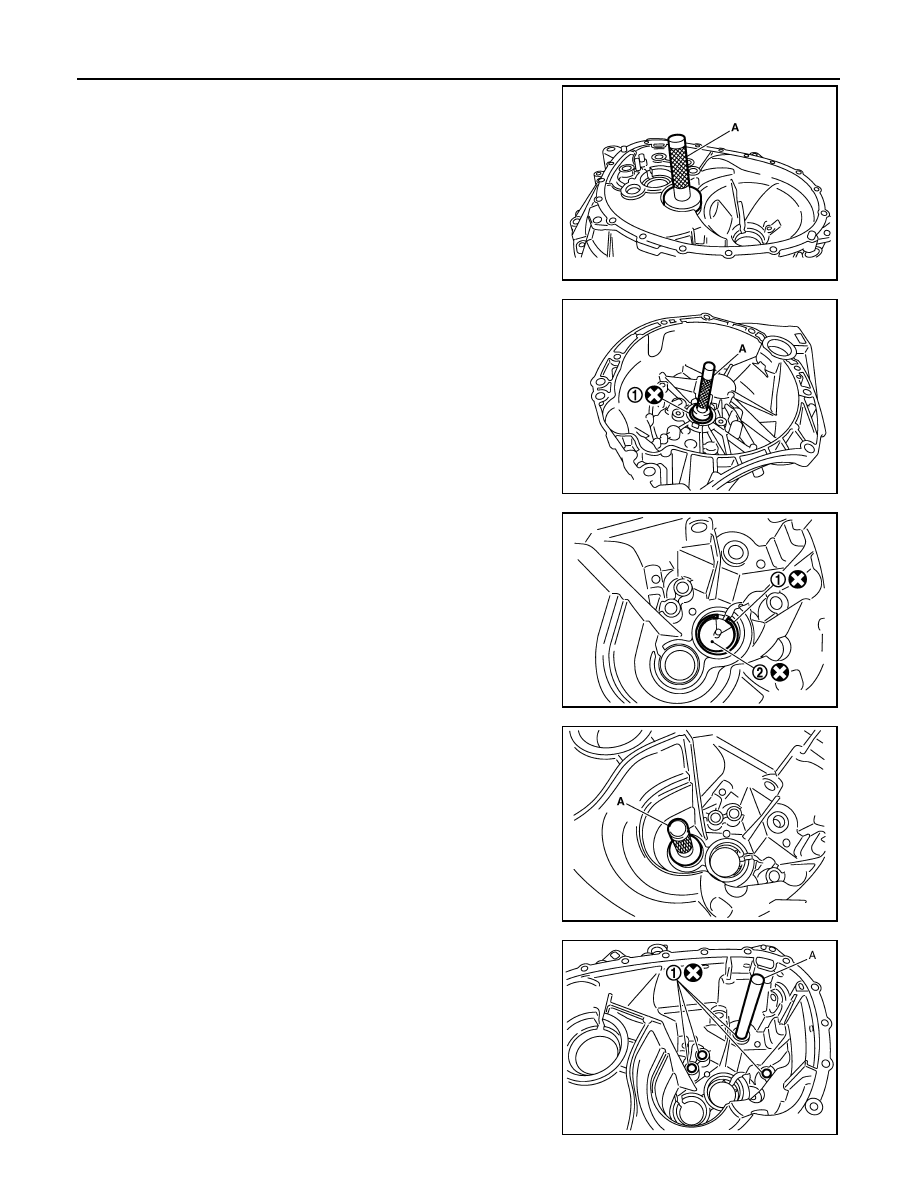
5.
Install oil channel and mainshaft front bearing outer race into
clutch housing using the drift (A) [SST: KV38100200].
CAUTION:
• Never reuse oil channel.
• Replace mainshaft front bearing outer race and mainshaft
front bearing inner race as a set.
6.
Install input shaft oil seal (1) into clutch housing using the drift
(A) [SST: ST33220000].
7.
Install snap ring (1) and oil channel (2) onto transaxle case.
8.
Install bearing preloading shim and mainshaft rear bearing outer
race into transaxle case using the drift (A) [SST: KV38100200].
CAUTION:
Replace mainshaft rear bearing outer race and mainshaft
rear bearing inner race as a set.
9.
Install bushings (1) into transaxle case using the drift (A) [Com-
mercial service tool].
PCIB1724E
PCIB1721E
PCIB1729E
PCIB1728E
JPDIC0109ZZ