Content .. 2179 2180 2181 2182 ..
Nissan Qashqai J11. Manual - part 2181
DAS-138
< DTC/CIRCUIT DIAGNOSIS >
[DRIVER ASSISTANCE SYSTEM]
U111C FRONT CAMERA IMAGE SIGNAL CIRCUIT
4.
Check continuity between around view monitor control unit connector and ground.
Is the inspection result normal?
YES
>> GO TO 4.
NO
>> Repair or replace harness or connectors.
4.
CHECK FRONT CAMERA IMAGE SIGNAL
1.
Connect around view monitor control unit and front camera connectors.
2.
Turn ignition switch ON.
3.
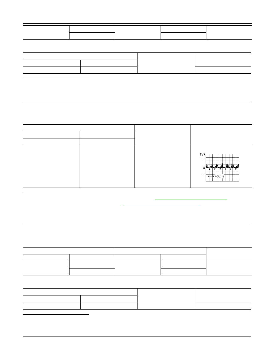
Check signal between the terminals of around view monitor control unit connector.
Is the inspection result normal?
YES
>> Replace around view monitor control unit. Refer to
AV-267, "Removal and Installation"
NO
>> Replace front camera unit. Refer to
DAS-201, "Removal and Installation"
.
WITHOUT PUMP CONTROL UNIT
1.
CHECK FRONT CAMERA POWER SUPPLY AND GROUND CIRCUIT CONTINUITY
1.
Turn ignition switch OFF.
2.
Disconnect around view monitor control unit and front camera connectors.
3.
Check continuity between around view monitor control unit connector and front camera connector.
4.
Check continuity between around view monitor control unit connector and ground.
Is the inspection result normal?
YES
>> GO TO 2.
NO
>> Repair or replace harness or connectors.
2.
CHECK FRONT CAMERA POWER SUPPLY VOLTAGE
1.
Connect around view monitor control unit and front camera connectors.
M8
71
E106
4
Existed
72
5
Around view monitor control unit
Ground
Continuity
Connector
Terminal
M8
71
Not existed
Around view monitor control unit connector
Condition
Reference value
(+)
(
−
)
Terminal
Terminal
71
72
CAMERA switch is ON or se-
lector lever in R (reverse).
JSNIA0834GB
Around view monitor control unit
Front camera
Continuity
Connector
Terminals
Connector
Terminals
M95
38
E106
2
Existed
37
1
Around view monitor control unit
Ground
Continuity
Connector
Terminal
M95
38
Not existed