Content .. 1350 1351 1352 1353 ..
Nissan Juke F15. Manual - part 1352
V
T
L
- 1
4
< REMOVAL AND INSTALLATION >
BLOWER MOTOR
BLOWER MOTOR
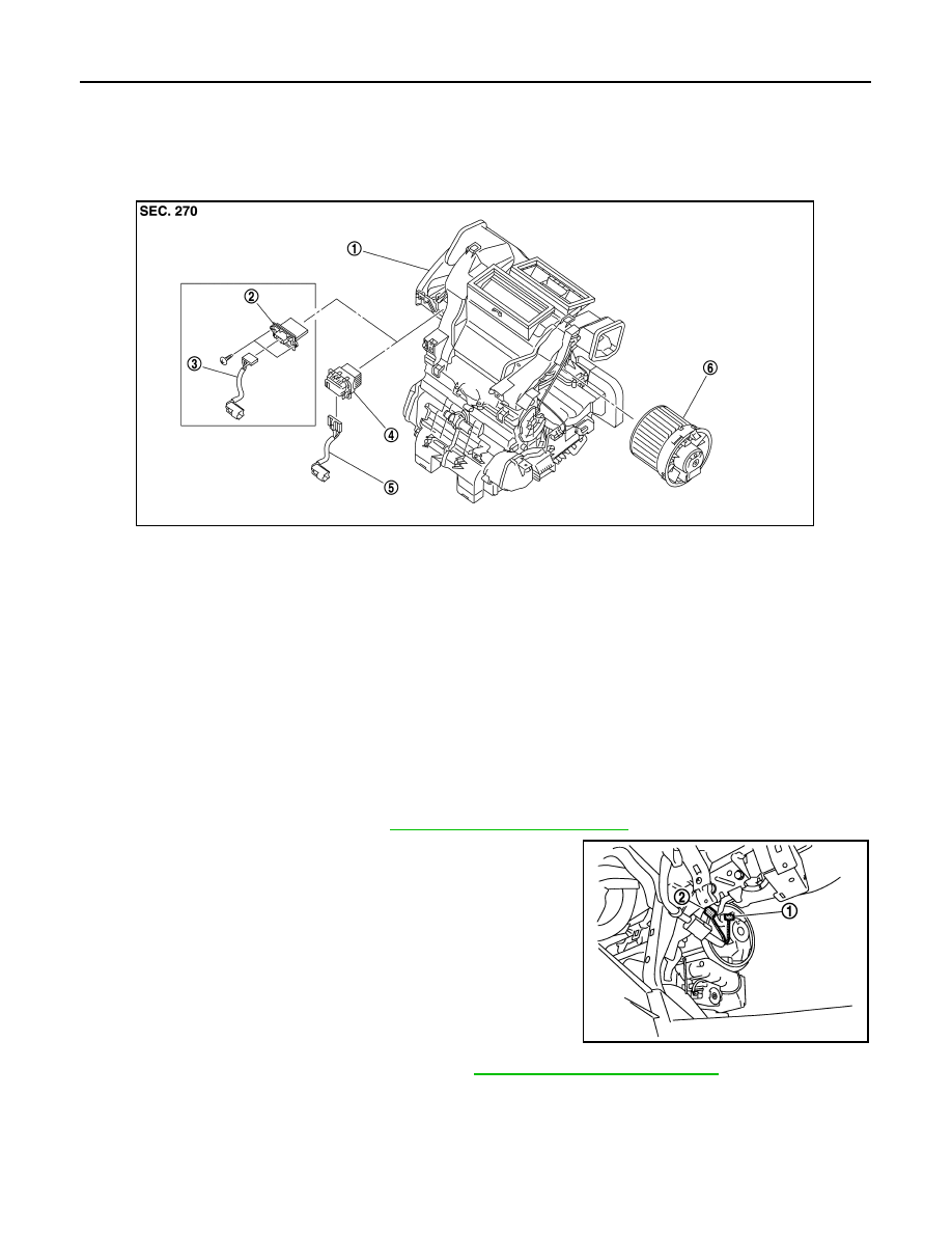
Exploded View
INFOID:0000000012199152
*1: Manual air conditioning
*2: Automatic air conditioning
Removal and Installation
INFOID:0000000012199153
WARNING:
• Before servicing, turn ignition switch OFF, disconnect battery negative terminal and wait 3 minutes
or more.
• Always work from the side of air bag module. Never work in front of it.
• Never use the air tools or the electric tools for servicing.
REMOVAL
1. Remove glove box assembly. Refer to
IP-13, "Removal and Installation"
2. Disconnect blower motor harness connector (1) and front pas-
senger air bag module harness connector (2).
3. Remove front passenger air bag module. Refer to
SR-18, "Removal and Installation"
1.
A/C unit assembly
2.
Blower fan resistor
*1
3.
Sub harness
*1
4.
Power transistor
*2
5.
Sub harness
*2
6.
Blower motor
JPIIA1549ZZ
JMIIA1044ZZ