LG936L Wheel Loader. Manual - part 16
 

  Index      SDLG     LG936L Wheel Loader - service repair manual


Search            


Content   ..  14  15  16  17   ..


LG936L Wheel Loader. Manual - part 16


Operation & Maintenance Manual──LG936L Wheel Loader 

 60


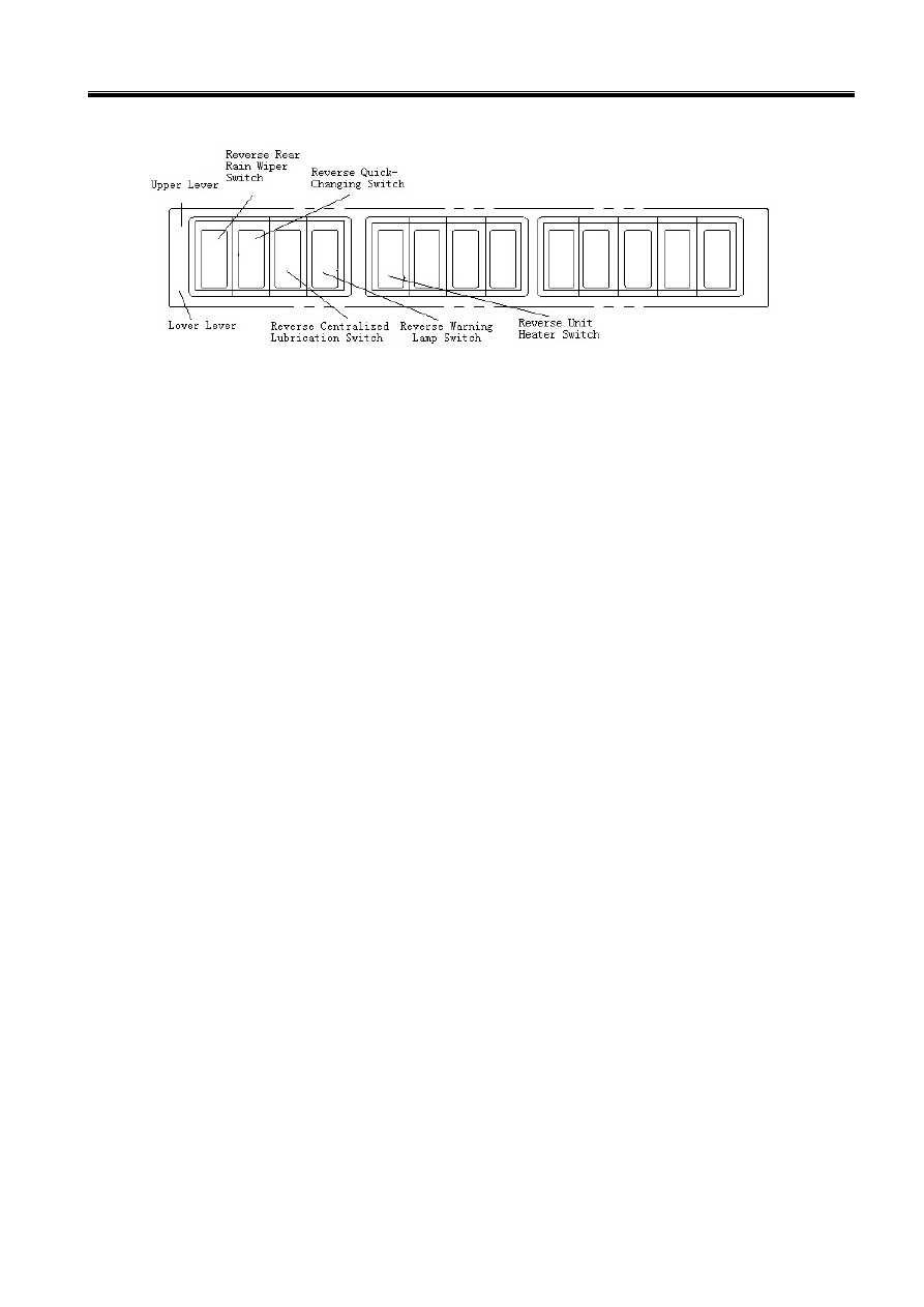
z  Unit Heater Switch (if assembled): 

Press the lower button and unit heater will work; press upper button, and unit heater stops 

working. When the unit heater or air-condition work, adjust the air outlet in the front or profile of 

gauge panel. Adjust wind outlet to clean the frost and blow the warm (cool) wind. 

z  Water Spraying Switch: 

Press bottom side, the water spraying engine begins working and water is sprayed from the 

spraying port of rain wiper to clean the glass of the cab; If loose, the switch will return 

automatically to stop spraying. 

z  Rear Headlight Switch: 

Press bottom side, and low beam of the rear headlight will come on;   

Press top side, and the high beam of the rear headlight will come on. 

If no side is pressed, no lamp will come on. 

z  Front Headlight Switch(if assembled): 

Press bottom side, and low beam of the front headlight will come on;   

Press top side, and the high beam of the front headlight will come on. 

If no side is pressed, no lamp will come on. 

z  Front (Rear) Lighting Lamp Switch: 

Press bottom side, and the front (rear) lighting lamp will come on; press top side and the lamp 

will go off. 

z  Back Light Switch(if assembled): 

Press bottom side, the back light lamp and the head and tail lights will come on; press top side, 

the lamps will go off. 

z  Warning Lamp Switch(if assembled): 

When this button is pushed down, all the turning lamps will blink for an emergency circumstance, 

sending light to warn the other vehicles and passersby. Press the button once again and the button 

springs back, so all the turning lamps will stop blinking. 

Operation & Maintenance Manual──LG936L Wheel Loader 

 61

z  Warning Button Switch: 

When this button is pushed down, all the turning lamps will blink for an emergency circumstance, 

sending light to warn the other vehicles and passersby. Press the button once again and the button 

springs back, so all the turning lamps will stop blinking. 

z  Rain wiper Switch: 

Press bottom side, rain wiper will work; press top side, the rain wiper will stop. 

z  Water Spraying Switch: 

Press bottom side, spray water to the front glass of the cab; press top side, stop spraying. 

z  Top Lamp Switch: 

This switch is behind the ceiling lamp in the operator 

cab. 

Press ON position to turn it on. 

Press OFF position to turn it off. 

Turn it OFF during driving. 

z  Fan Switch: 

Press the bottom side, for low air speed; 

Press the top side, for high air speed; 

Press the middle of the button, and the fan will stop. 

z  Horn Switch: 

Press the button in the middle of the steering wheel, and the horn will sound.   

z  Power Switch 

The switch locates in the right battery box. The power of 

the whole vehicle is shut off when the switch turns to the 

‘ ’ position; The power of the whole vehicle is turn on 

when the switch turns to the ‘ ’ position. Please shut the 

power switch if park the vehicle for a long time. The 

position shown in the figure is the state of shut off. 


1.2.3 Steering Wheel 

The steering wheel is in the operator cab. Refer to 

1.1 General View of Controls and 

Gauges Figure 3-1

 in this chapter. The steering wheel and steering unit are connected. 

Turning the steering wheel clockwise, the machine turns right; turning the steering wheel 

counter-clockwise, the machine turns left. 

The features are listed below: 

z  The rotation angles of the steering wheel and the machine are not equal. If the steering wheel is 

Operation & Maintenance Manual──LG936L Wheel Loader 

 62

continuously turned; the machine rotation angle will increase until at the needed position.   

z  The faster the steering wheel turns, the faster the machine turns. 

z  The steering wheel will not automatically come back after turning, the turning angle of the 

machine will be kept. After finishing turning the machine, turn the steering wheel in the reverse 

direction to keep the machine moving in a straight direction. 

1.2.4 Control Levers and Pedals 

z  Shifting Control 

Lever 

This lever controls the 
direction and traveling 
speed of the machine. 
When the lever is at N (0) 
position, it means neutral 
gear. Put the control lever forward to the 1 position can obtain the forward gear Ⅰ, and the machine 
goes forward at low speed. When turn it to 2 position, the forward gear Ⅱ can be obtained, and the 
machine goes forward at high speed. Putting the lever to R position can obtain the reverse gear and 
the machine goes backward. 
z  Equipment Control Handle and Lever 

(1) Equipment Control Lever 

Refer to 

1.1 General View of Controls and Gauges Figure 3-1, Figure 3-2 

in this 

chapter. 

‹  Bucket Control Lever 

This lever controls the bucket which has 

three positions. 

—  Rear Tilt is used for drawing in 

the bucket 

—  Neutral is used for keeping the 

bucket in the desired position. 

—  Forward Tilt is used for dumping. 

‹  Lift Arm Control Lever 

This lever controls the lift arm, which has 

four positions.


—  Lift is used for lifting. 

—  Neutral is used for maintaining the  Position of Bucket 

Control Lever 

Position of Lift Arm
Control Lever 

Operation & Maintenance Manual──LG936L Wheel Loader 

 63

bucket in the desired position. 

—  Lower is used for lowering. 

—  Float is used for moving freely under applied force. 

Notice:  

Do not lower the arm at float position. 


(2) Equipment Control Handle 

Refer to 

1.1 General View of   

Controls and Gauges Figure 3-1, Figure 3-2

 in this 

chapter. 

This handle controls the bucket and lift arm. There are four gears 

to control the lift, neutral, lower and float of the lift arm pro-and 

post, and there are three gears to control the forward tilt, neutral 

and rear tilt of the bucket from left to right. 

Lift Arm: 

Lift is used for lifting. 

Neutral is used for maintaining the lift arm in the desired 

position. 

Lower is used for lowering. 

Float is used for moving freely under applied force. 

Notice: Do not lower the arm at float position. 

Bucket: 

Rear Tilt is used for drawing in the bucket 

Neutral is used for keeping the bucket in the desired position. 

Forward Tilt is used for dumping. 

The working device control handle also has the following functions: 

—  Lifting limit location function: When place the control handle in the lifting position, the 

magnetic force from lifting limit location locked magnet coil of pilot valve can lock the 

control level in the lifting position; When the lift arm lifts to the highest position, the control 

handle turn to neutral position to realize the lifting limit to prevent the equipment from injury 

by hydraulic impact. 

—  Set level automatically function: When dumping in the highest position, move the control 


Content   ..  14  15  16  17   ..