LG936L Wheel Loader. Manual - part 15
 

  Index      SDLG     LG936L Wheel Loader - service repair manual


Search            


Content   ..  13  14  15  16   ..


LG936L Wheel Loader. Manual - part 15


Operation & Maintenance Manual──LG936L Wheel Loader 

 56

If the pressure index lies in the green range 

(11~15)×100kPa or (15.95~21.75)×10PSI

, the oil 

pressure is normal. Be sure to stop the machine for inspection if the 

index moves outside this range. 


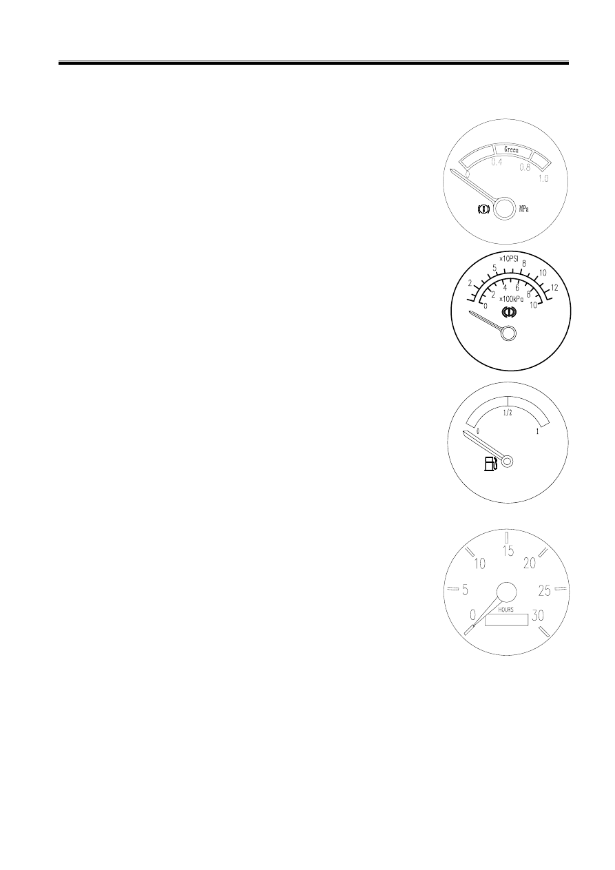
z  Brake Air Pressure Gauge 

This gauge indicates the air pressure of the brake system. 

If the pressure index lies in the green range (0.4MPa~0.8MPa), the oil 

pressure is normal. Be sure to stop the machine for inspection if the 

index moves outside this range. 

This gauge indicates the air pressure of the brake system. 

If the pressure index lies in the green range 

(4~8)×100kPa or (5.8~

11.6)×10PSI

, the oil pressure is normal. Be sure to stop the machine for 

inspection if the index moves outside this range. 

z  Fuel Level Gauge (if assembled) 

This gauge indicates the ratio of remaining fuel level in the fuel tank 

to the volume of tank.   


z  Revolution Indicator (if assembled) 

This gauge indicates the rotating speed of engine 


z  Indicator Lamp   

The indicator lamp is located on the gauge panel. Refer to 

1.1 General View of Controls 

and Gauges Figure3-2 

in this chapter. 


Operation & Maintenance Manual──LG936L Wheel Loader 

 57


z  Pre-heat Indicator Lamp: If assemble the pre-heat function, the lamp would be on if in the 

pre-heating state or the light will be off.   

z  Oil Pressure Warning Lamp: The lamp will come on immediately if the start switch is turned 

on. It will go off immediately after the engine is started. Otherwise it means the level of lubricant 

is too low or there is some problem with the lubricant system. Then shut the engine and check it. 

z  Charging Indicator Lamp: The lamp will come on if the start switch is turned on. It will go off 

immediately after the engine is started. Otherwise it means there is some problem with storage 

battery. Please examine and repair it. 

z  Power Cut Indicator Lamp: The lamp will come on if the power is cut off, and it will go off if 

the power is not cut off. 

The power will be cut off and the lamp will come on if the left braking pedal is stepped down; the 

power will not be cut off and the lamp will go off if the right braking pedal is stepped down. 

z  Emergency Steering Indicator Lamp: The emergency steering function is selected to install. 

When the wheel loader is steered emergently, the lamp will come on if the emergency steering 

pump works.   

z  Parking Brake Indicator Lamp: The lamp will come on when the parking brake switch is 

pushed down and the brake air pressure is low. The lamp will go off when the brake air pressure 

is normal and the parking brake switch springs back. 

z  Low Brake Air Pressure Alarm Lamp: The lamp will come on for a warning if the brake air 

pressure is below 0.4MPa. 

z  High Beam Indicator Lamp: The lamp will come on if the high beam is used in the front 

headlight. The lamp will be off if the dipped headlight is used or the front headlight is off. 

z  Computer working Indicator Lamp: If ZF gear box or 4WG180 gear box is assembled, the 

lamp will come on when the starting switch is on, otherwise examine and repair it. 

Operation & Maintenance Manual──LG936L Wheel Loader 

 58

z  Fuel Prefiltration Indicator Lamp: The lamp will come on when the fuel preliminary filter is 

blocked. Please clean it or replace.   


1.2.2 Switch 

z  Starting Switch 

This switch, on the gauge panel, is used for starting or shutting 

down the electric system and the engine. Refer to 

1.1 General 

View of Controls and Gauges Figure3-1, Figure3-2, 

Figure3-3 

in this chapter. 

HEAT Position 

This position is used for the pre-heating system if the machine has 

the cold-start function. 

OFF Position 

Insert or remove the key in this position. Turn the key to this position to cut off the electric 

power. 

ON Position 

This position is used to turn on the electric system. Keep the key in this position when the 

engine is running. 

START Position 

This is the engine-start position. Keep the key at this position during starting. After the engine 

has started, immediately pull out the key, or it will return to ON position automatically.   

z  Radio and CD Player (selectable) 

This switch is at the right side of the ceiling cab, and for the details please refers to Radio and 

CD Player Assemble & Operation Manual. Vehicle without radio, the connection of radio is 

obligated and further assembly can be carried out by professional workers according to the   

z  Turning Switch (selectable) 

Push this switch forward, and the left turning lamp lights. Push this switch backward, and the 

right turning lamp lights. Refer to 

1.1 Control System and the Gauge in the chapter, 

Figure3-1, Figure3-2

z  Switch Group (if assembled) 

Refer to 

1.1 Control System and the Gauge Figure 3-3 in this chapter.

 The switch 

controls lighting, high and low beam and steering light. 

‹  Lighting 

Operation & Maintenance Manual──LG936L Wheel Loader 

 59

When the starting switch is in the ON position, 

the high beam of front headlight is lightened if 

the switch group turns to OFF and put it up; the 

head light, tail light and back light is lightened if 

the switch group turns to the position of ‘

’ or 

’. The high beam of front headlight lights if put it up. 

‹  Control of high and low light 

When the starting switch is in the ON position and switch group turns to the position of‘

, the 

low beam of front headlight is lightened; the high beam of front headlight is lightened when put 

the switch down.   

‹  Control of turning lamp 

The left turning lamp is lightened when the switch is put forward, and the right turning lamp is 

lightened when the switch is put backward. 

Notice: 

The turn indicator lamp is lightened when operate the switch. After the operation of turning finished, 

please put back the switch by your hand. 
z  Rocker Switches 

The rocker switch includes rocker switch on gauges and the one on right front side of the cab top. The 

switches on the gauges refer to 1.1 Control System and the Gauge Figure 3-5 in this chapter. When 

the start switch is at ON position, the spray, rain wiper, rear lighting lamp, front lighting lamp, rear 

headlight, warning lamp are under control; the rocker switch at right front side of the cab top refers to 

the figure below, when the start switch is at ON position, the unit heater, the spray, front and back 

headlight lamp, rear lighting lamp, front lighting lamp,back light, warning lamp and rain wiper will 

be controlled separately by this switch. 


Content   ..  13  14  15  16   ..