Mitsubishi Outlander XL. Manual - part 1135


  Index      Mitsubishi     Mitsubishi Outlander XL - service repair manual 2007 year


Search            


Content   ..  1133  1134  1135  1136   ..


Mitsubishi Outlander XL. Manual - part 1135
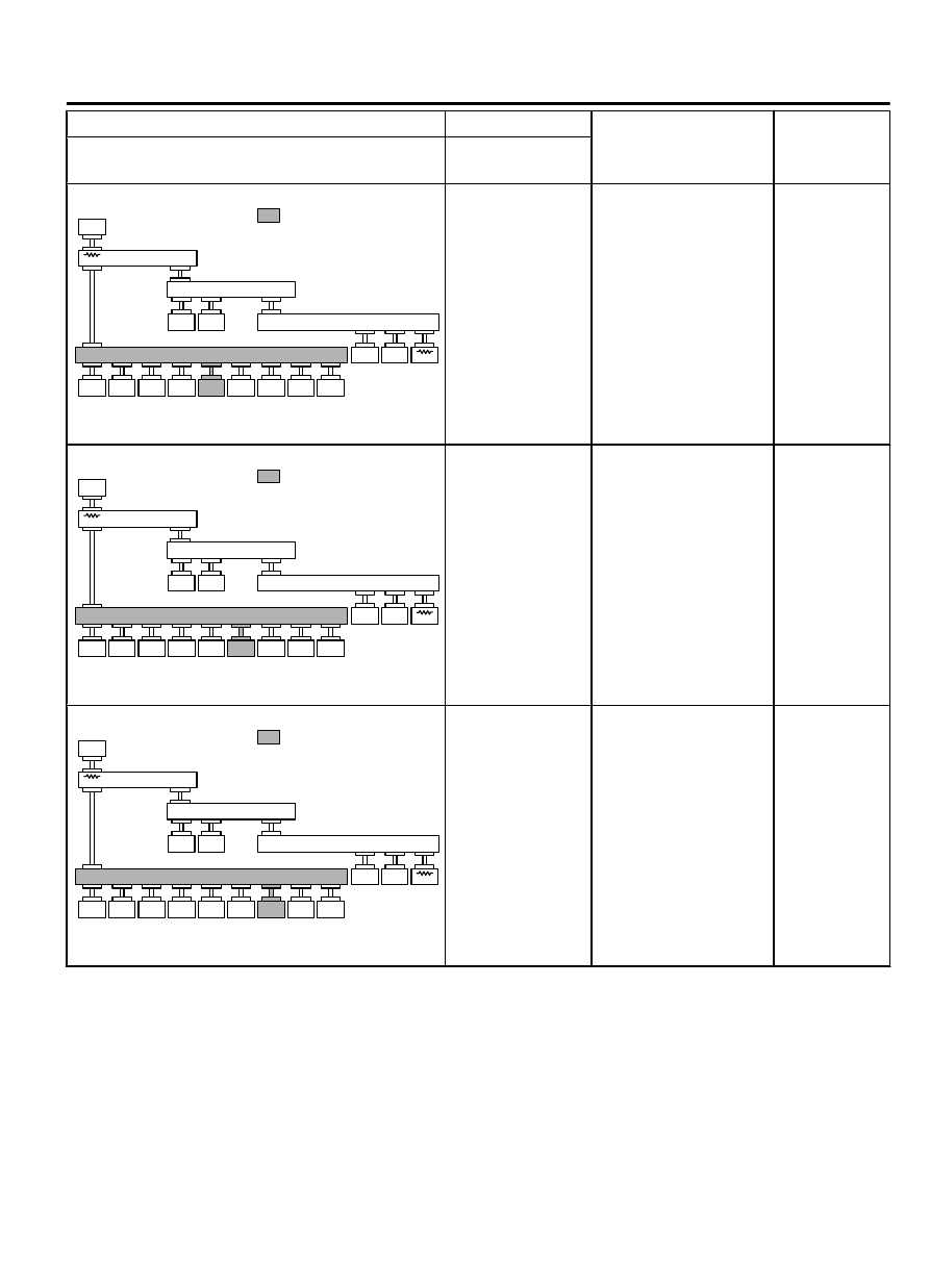


Scan tool screen

Diagnosis detail

Reference
page

(The  ECUs  that  are  not  adopted  are  not
displayed).

Comment

ZC5018550014

: Red section on scree n

M. U.T.

J/C (3)

J/C (2)

SAS

4WD

K OS/WC

M

SRS

OCM

A/C

AUDI O

MMCS

Sat Radio

HFM

METER

ABS/ASC

AT

ENGINE

ETACS

J/C (1)

CAN-B:
Disconnection  in
red

 displayed

area is estimated.

Diagnostic item 20
Diagnose  when  the
scan

 tool

 cannot

receive  the  data  sent
by radio and CD player
or CD changer

 P.54D-107

ZC5018550015

: Red section on scree n

M. U.T.

J/C (3)

J/C (2)

SAS

4WD

K OS/WC

M

SRS

OCM

A/C

AUDI O

MMCS

Sat Radio

HFM

METER

ABS/ASC

AT

ENGINE

ETACS

J/C (1)

CAN-B:
Disconnection  in
red

 displayed

area is estimated.

Diagnostic item 21
Diagnose  when  the
scan

 tool

 cannot

receive  the  data  sent
by CAN box unit

 P.54D-110

ZC5018550016

: Red section on scree n

M. U.T.

J/C (3)

J/C (2)

SAS

4WD

K OS/WC

M

SRS

OCM

A/C

AUDI O

MMCS

Sat Radio

HFM

METER

ABS/ASC

AT

ENGINE

ETACS

J/C (1)

CAN-B:
Disconnection  in
red

 displayed

area is estimated.

Diagnostic item 22
Diagnose  when  the
scan

 tool

 cannot

receive  the  data  sent
by satellite radio tuner

 P.54D-113

CONTROLLER AREA NETWORK (CAN)

54D-23

DIAGNOSIS

Scan tool screen

Diagnosis detail

Reference
page

(The  ECUs  that  are  not  adopted  are  not
displayed).

Comment

ZC5018550017

: Red section on scree n

M. U.T.

J/C (3)

J/C (2)

SAS

4WD

K OS/WC

M

SRS

OCM

A/C

AUDI O

MMCS

Sat Radio

HFM

METER

ABS/ASC

AT

ENGINE

ETACS

J/C (1)

CAN-B:
Disconnection  in
red

 displayed

area is estimated.

Diagnostic item 23
Diagnose  when  the
scan

 tool

 cannot

receive  the  data  sent
by hands free module

 P.54D-116

ZC5018550018

: Red section on scree n

M. U.T.

J/C (3)

J/C (2)

SAS

4WD

K OS/WC

M

SRS

OCM

A/C

AUDI O

MMCS

Sat Radio

HFM

METER

ABS/ASC

AT

ENGINE

ETACS

J/C (1)

CAN-B:  A  failure
in the red section,
or a bus-off failure
is  present  in  the
gateway ECU.

Diagnostic item 24
Short to power supply
or  ground  in  both
CAN_H  and  CAN_L
lines.

 P.54D-119

ZC5018550019

: Red section on scree n

M. U.T.

J/C (3)

J/C (2)

SAS

4WD

K OS/WC

M

SRS

OCM

A/C

AUDI O

MMCS

Sat Radio

HFM

METER

ABS/ASC

AT

ENGINE

ETACS

J/C (1)

CAN-B:
Disconnection  in
red

 displayed

area is estimated.

Diagnostic item 25
Diagnose the ETACS-
ECU,  joint  connector
(CAN1)

 or

 lines

between  ETACS-ECU
and  joint  connector
(CAN1)

 P.54D-149

54D-24

CONTROLLER AREA NETWORK (CAN)

DIAGNOSIS

Scan tool screen

Diagnosis detail

Reference
page

(The  ECUs  that  are  not  adopted  are  not
displayed).

Comment

ZC5018550018

: Red section on scree n

M. U.T.

J/C (3)

J/C (2)

SAS

4WD

K OS/WC

M

SRS

OCM

A/C

AUDI O

MMCS

Sat Radio

HFM

METER

ABS/ASC

AT

ENGINE

ETACS

J/C (1)

CAN-B:
Disconnection  in
red

 displayed

area is estimated.

Diagnostic item 26
Short to power supply
or ground, open circuit
or  line-to-line  short  in
the CAN-B bus lines

 P.54D-153

CAN BUS DIAGNOSTICS

DIAGNOSTIC ITEM 1: Diagnose when the scan tool cannot receive the data sent by
ETACS-ECU

M15408300006USA0000010000

When servicing a CAN bus line, ground yourself
by touching a metal object such as an unpainted

water  pipe.  If  you  fail  to  do  so,  a  component
connected to the CAN bus line may be damaged.

CAN Communication Circuit

ETACS-ECU

DATA LINK
CONNECTOR

CAN DRIVE
CIRCUIT

INTERFACE
CIRCUIT

FRONT SIDE

CONTROLLER AREA NETWORK (CAN)

54D-25

DIAGNOSIS

ZC6008750000

Connector: C-125

C-125 (B)

ZC6008780000

Connector: C-301


FUNCTION
When the CAN bus diagnosis is carried out, the scan
tool  communicates  with  the  ETACS-ECU.  If  a
communication flag is not set for the ETACS-ECU, the
ETACS-ECU will be diagnosed as a communication
error.

TROUBLE JUDGEMENT CONDITIONS
If a communication flag is not set for the ETACS-ECU,
the ETACS-ECU determines that there is a failure.

TROUBLESHOOTING HINTS

Malfunction of the connector (data link connector or
ETACS-ECU connector improperly connected)

Malfunction  of  the  wiring  harness  (open  circuit,
short to ground, short to power supply between the
data  link  connector  and  the  ETACS-ECU
connector, line-to-line short, or power supply to the
ETACS-ECU)

Malfunction of ETACS-ECU

DIAGNOSIS

Required Special Tools:

MB991223: Harness Set

MB992006: Extra Fine Probe

MB991958: Scan Tool (M.U.T.-III Sub Assembly)

MB991824: Vehicle Communication Interface (V.C.I.)

MB991827: M.U.T.-III USB Cable

MB991910: M.U.T.-III Main Harness A

STEP 1. Check data link connector C-125 and ETACS-ECU
connector C-301 for loose, corroded or damaged terminals,
or terminals pushed back in the connector.

The strand end of the twisted wire should be within 10 cm
(4 inches) from the connector. For details refer to P.54D-8.

Q:Are data link connector C-125 and ETACS-ECU connector

C-301 in good condition?

YES:

 Go to Step 2.

NO:

 Repair the damaged parts.

STEP 2. Check the wiring harness between data link
connector C-125 and ETACS-ECU connector C-301.

Strictly  observe  the  specified  wiring  harness  repair
procedure. For details refer to P.54D-8.

54D-26

CONTROLLER AREA NETWORK (CAN)

DIAGNOSIS


Content   ..  1133  1134  1135  1136   ..