Mitsubishi Outlander GS45X. Manual - part 745
 

  Index      Mitsubishi     Mitsubishi Outlander GS45X - service repair manual


Search            


Content   ..  743  744  745  746   ..


Mitsubishi Outlander GS45X. Manual - part 745


MULTIPORT FUEL INJECTION (MFI) DIAGNOSIS

TSB Revision

MULTIPORT FUEL INJECTION (MFI) <2.4L ENGINE>

13A-803

STEP 19. Check harness connector B-10 at ECM connector 
for damage.
Q: Is the connector in good condition?

YES : Check harness connector A-13 at intermediate 

connector for damage, and repair or replace as 
required. Refer to, GROUP 00E, Harness Connector 
Inspection 

P.00E-2

. If intermediate connector is in 

good condition, repair harness wire between ECM 
connector B-10 (terminal No. 6) and starter relay 
connector A-27X (terminal No. 2) because of short 
circuit to ground. Then confirm that the malfunction 
symptom is eliminated.

NO :  Repair or replace it. Refer to GROUP 00E, Harness 

Connector Inspection 

P.00E-2

. Then confirm that the 

malfunction symptom is eliminated.

STEP 20. Check harness connector B-114 at starter 
connector for damage.
Q: Is the connector in good condition?

YES : Go to Step 21.
NO :  Repair or replace it. Refer to GROUP 00E, Harness 

Connector Inspection 

P.00E-2

. Then confirm that the 

malfunction symptom is eliminated.

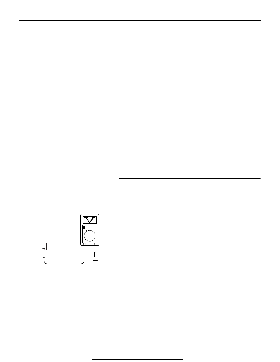
STEP 21. Measure the power supply voltage at starter 
harness side connector B-114.
(1) Disconnect the connector B-114 and measure at the 

harness side.

(2) Turn the ignition switch to the "START" position.
(3) Measure the voltage between terminal No. 1 and ground.

• Voltage should be battery positive voltage

(4) Turn the ignition switch to the "LOCK" (OFF) position.
Q: Is battery positive voltage (approximately 12 volts) 

present?
YES : 
Go to Step 26.
NO :  Go to Step 22.

1

AK704321

B-114 harness
connector:
component side

AB

MULTIPORT FUEL INJECTION (MFI) DIAGNOSIS

TSB Revision

MULTIPORT FUEL INJECTION (MFI) <2.4L ENGINE>

13A-804

STEP 22. Measure the power supply voltage at starter relay 
harness side connector A-27X.
(1) Disconnect the connector A-27X and measure at the 

harness side.

(2) Measure the voltage between terminal No. 4 and ground.

• Voltage should be battery positive voltage

Q: Is battery positive voltage (approximately 12 volts) 

present?
YES : 
Go to Step 23.
NO :  Repair harness wire between fusible link (24) and 

starter relay connector A-27X (terminal No. 4) 
because of open circuit or short circuit to ground. 
Then confirm that the malfunction symptom is 
eliminated.

STEP 23. Check for open circuit and short circuit to 
ground between starter relay connector A-27X (terminal 
No. 3) and starter connector B-114 (terminal No. 1)
NOTE: Check harness after checking intermediate connector 
A-13, B-23. If intermediate connector is damaged, repair or 
replace it. After to GROUP 00E, Harness Connector Inspection 

P.00E-2

. Then check that the malfunction is eliminated.

Q: Is the harness wire in good condition?

YES : Go to Step 24.
NO :  Repair it. Then confirm that the malfunction symptom 

is eliminated.

STEP 24. Check harness connector B-11 at ECM connector 
and harness connector B-110 at transmission range switch 
connector for damage.
Q: Is the connector in good condition?

YES : Go to Step 25.
NO :  Repair or replace it. Refer to GROUP 00E, Harness 

Connector Inspection 

P.00E-2

. Then confirm that the 

malfunction symptom is eliminated.

2

1

3
4

AK700519AB

A-27X harness
connector:
component side

MULTIPORT FUEL INJECTION (MFI) DIAGNOSIS

TSB Revision

MULTIPORT FUEL INJECTION (MFI) <2.4L ENGINE>

13A-805

STEP 25. Check for harness damage between ECM 
connector B-11 (terminal No. 106) and transmission range 
switch connector B-110 (terminal No. 10).
NOTE: Check harness after checking intermediate connector 
A-13. If intermediate connector is damaged, repair or replace it. 
After to GROUP 00E, Harness Connector Inspection 

P.00E-2

Then check that the malfunction is eliminated.
Q: Is the harness wire in good condition?

YES : Check harness connector A-13 at intermediate 

connector for damage, and repair or replace as 
required. Refer to, GROUP 00E, Harness Connector 
Inspection 

P.00E-2

. If intermediate connector is in 

good condition, repair harness wire between 
transmission range switch connector B-110 (terminal 
No. 7) and starter relay connector A-27X (terminal No. 
2) because of harness damage. Then confirm that the 
malfunction symptom is eliminated.

NO :  Repair it. Then confirm that the malfunction symptom 

is eliminated.

STEP 26. Check for harness damage between starter relay 
connector A-27X (terminal No. 3) and starter connector 
B-114 (terminal No. 1)
NOTE: Check harness after checking intermediate connector 
A-13, B-23. If intermediate connector is damaged, repair or 
replace it. After to GROUP 00E, Harness Connector Inspection 

P.00E-2

. Then check that the malfunction is eliminated.

Q:  Is the harness wire in good condition?

YES : Go to Step 27.
NO :  Repair it. Then confirm that the malfunction symptom 

is eliminated.

STEP 27. Check for harness damage between fusible link 
(24) and starter relay connector A-27X (terminal No. 4)
Q: Is the harness wire in good condition?

YES : Go to Step 28.
NO :  Repair it. Then confirm that the malfunction symptom 

is eliminated.

STEP 28. Check harness connector B-113 at starter 
connector for damage.
Q: Is the connector in good condition?

YES : Go to Step 29.
NO :  Repair or replace it. Refer to GROUP 00E, Harness 

Connector Inspection 

P.00E-2

. Then confirm that the 

malfunction symptom is eliminated.

MULTIPORT FUEL INJECTION (MFI) DIAGNOSIS

TSB Revision

MULTIPORT FUEL INJECTION (MFI) <2.4L ENGINE>

13A-806

STEP 29. Check for open circuit and short circuit to 
ground and harness damage between battery and starter 
connector B-113 (terminal No. 1)
Q: Is the harness wire in good condition?

YES : Replace the starter.
NO :  Repair it. Then confirm that the malfunction symptom 

is eliminated.


Content   ..  743  744  745  746   ..