Mitsubishi Outlander GS45X. Manual - part 162


  Index      Mitsubishi     Mitsubishi Outlander GS45X - service repair manual


Search            


Content   ..  160  161  162  163   ..


Mitsubishi Outlander GS45X. Manual - part 162


USB BOX

TSB Revision

CHASSIS ELECTRICAL

54A-645

The USB adapter data cannot be replayed. <Vehicles with MMCS>

CAUTION

Before replacing the USB box, ensure that the power supply circuit, the ground circuit and the com-
munication circuit are normal.

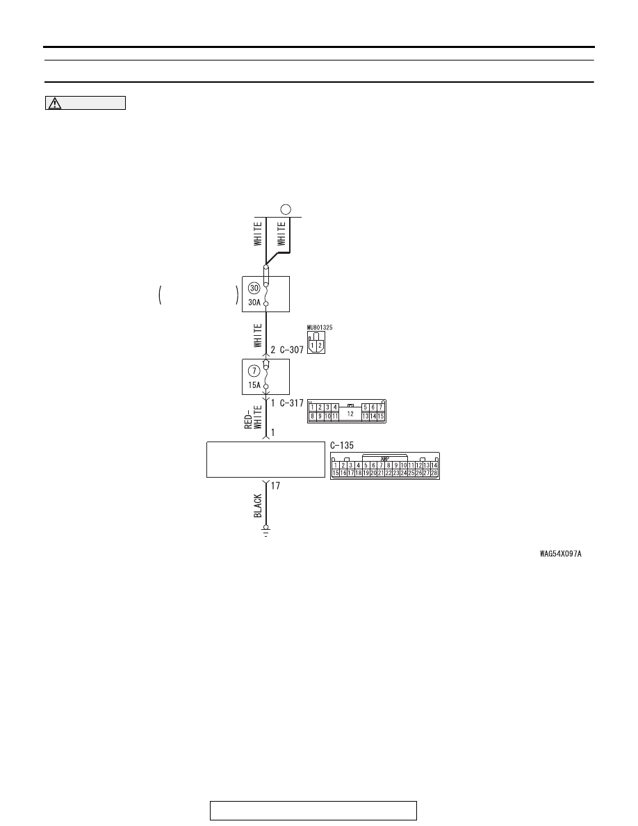
USB Box Power Supply Circuit

FUSIBLE 
LINK

36

USB BOX

ENGINE 
COMPARTMENT

RELAY BOX

ETACS-
ECU

USB BOX

TSB Revision

CHASSIS ELECTRICAL

54A-646

.

COMMENTS ON TROUBLE SYMPTOM

If the sound replay is impossible with the USB/iPod 
mode, the USB adapter, USB cable, USB box, or 
multivision display may be defective, or a communi-
cation error between the multivision display and USB 
box may have occurred.

.

PROBABLE CAUSES

• The multivision display may be defective.

• The USB box may be defective.

• The USB adapter may be defective.

• The USB cable may be defective.

• Damaged harness wires and connectors

DIAGNOSIS

Required Special Tools:

• MB991223: Harness Set

• MB992006: Extra Fine Probe

USB Box Communication Circuit

USB BOX

USB
ADAPTER

USB CABLE

MULTIVISION DISPLAY

ACA02654

AH

Connectors: C-06, C-07, C-15, C-135

C-06 (G)

C-135

C-07 (GR)

C-15

ACA02655AB

Connector: C-307, C-317

C-307 (B)

C-317

USB BOX

TSB Revision

CHASSIS ELECTRICAL

54A-647

STEP 1. Check the multivision display operation.
Check if the multivision display work normally and the sound is 
output.
Q: Is the check result normal?

YES : Go to Step 2.
NO :  Troubleshoot the MMCS (Refer to 

P.54A-486

).

STEP 2. Check the multivision display operation.
Display the A/V Mode screen, and check that the "USB/iPod" 
item is displayed.
Q: Is the check result normal?

YES : Go to Step 8.
NO :  Go to Step 3.

STEP 3. Check USB box connector C-135 for loose, 
corroded or damaged terminals, or terminals pushed back 
in the connector.
Q: IS hands USB box connector C-135 in good condition?

YES : Go to Step 4.
NO :  Repair the defective connector.

STEP 4. Check the power supply circuit to the USB box. 
Measure the voltage at USB box connector C-135.
(1) Disconnect USB box connector C-135, and measure the 

voltage available at the wiring harness side of the 
connector.

(2) Measure the voltage between terminal 1 and ground.

OK: The voltage should measure approximately 12 
volts (battery positive voltage).

Q: Is the measured voltage approximately 12 volts (battery 

positive voltage)?
YES : 
Go to Step 6.
NO :  Go to Step 5.

AC702831

Harness side: C-135

DO

USB BOX

TSB Revision

CHASSIS ELECTRICAL

54A-648

STEP 5. Check the wiring harness between USB box 
connector C-135 (terminal 1) and fusible link (36).

• Check the power supply lines (battery power supply) for 

open circuit and short circuit.

NOTE: Also check ETACS-ECU connector C-307, C-317 for 
loose, corroded, or damaged terminals, or terminals pushed 
back in the connector. If ETACS-ECU connector C-307, C-317 
is damaged, repair or replace the connector as described in 
GROUP 00E, Harness Connector Inspection 

P.00E-2

.

Q: Is the wiring harness between hands-free module 

connector C-135 (terminal 1) and fusible link (36) in 
good condition?
YES : 
The trouble can be an intermittent malfunction (Refer 

to GROUP 00, How to use 
Troubleshooting/inspection Service Points, How to 
Cope with Intermittent Malfunction 

P.00-15

).

NO :  The wiring harness may be damaged or the 

connector(s) may have loose, corroded or damaged 
terminals, or terminals pushed back in the connector. 
Repair the wiring harness as necessary.

STEP 6. Check the ground circuit to the USB box. Measure 
the resistance at hands USB box connector C-135.
(1) Disconnect USB box connector C-135, and measure at the 

wiring harness side.

(2) Measure resistance between terminal 17 and ground.

OK: The resistance should be 2 ohm or less.

Q: Is the measured resistance 2 ohms or less?

YES : Go to Step 8.
NO :  Go to Step 7.

STEP 7. Check the wiring harness between USB box 
connector C-135 (terminal 17) and ground.

• Check the body ground wires for open circuit.

Q: Is the wiring harness between USB box connector C-135 

(terminal 17) and ground in good condition?
YES : 
The trouble can be an intermittent malfunction (Refer 

to GROUP 00, How to use 
Troubleshooting/inspection Service Points, How to 
Cope with Intermittent Malfunction 

P.00-15

).

NO :  The wiring harness may be damaged or the 

connector(s) may have loose, corroded or damaged 
terminals, or terminals pushed back in the connector. 
Repair the wiring harness as necessary.

AC702818 EN

Harness side: C-135


Content   ..  160  161  162  163   ..