Mitsubishi Outlander GS45X. Manual - part 1041


  Index      Mitsubishi     Mitsubishi Outlander GS45X - service repair manual


Search            


Content   ..  1039  1040  1041  1042   ..


Mitsubishi Outlander GS45X. Manual - part 1041


TRIMS

TSB Revision

INTERIOR

52A-13

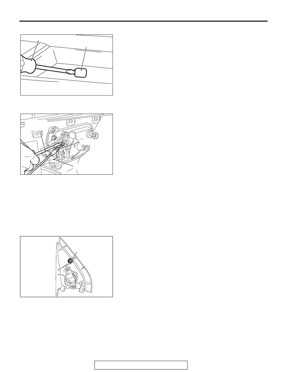
<<B>> DOOR TRIM CAP REMOVAL

Insert a flat-tipped (

−) screwdriver as shown in the figure to 

remove the door trim cap.

.

<<C>> FRONT/REAR DOOR TRIM REMOVAL

Using a flat-tipped (

−) screwdriver as shown in the figure, 

remove the inside lock cable and the inside handle cable, then 
remove the door trim.

INSTALLATION SERVICE POINTS

.

>>A<< POWER WINDOW SWITCH INSTALLATION

After the power window switch is installed or replaced, perform 
learning of the power window fully-closed position (Refer to 
GROUP 42A 

− Door Glass and Regulator 

P.42A-148

).

.

>>B<< FRONT DOOR SASH TRIM INSTALLATION

Install it with the clip attached as shown in the figure.

AC508380

Door trim cap

AB

Flat-tipped screwdriver

AC303180

Inside lock cable

Inside handle cable

AB

Flat-tipped 
screwdriver

AC507220AB

Clip

TRIMS

TSB Revision

INTERIOR

52A-14

LIFTGATE TRIM

REMOVAL AND INSTALLATION

M1521006500470

AC506882AC

1

2

3

4

5

6

7

6

1

B

B

Section A – A

Section E – E

Section F – F

Section G – G

Section H – H

Section B – B

Section C – C

Section D – D

5

6

A

A

5

C

C

6

E

E

1

F

F

4

G

G

2

H

H

7

D

D

Claw

Claw

Claw

Claw

Clip

Clip

Clip

Clip

Claw

Removal steps 

1.

Liftgate cover garnish

2.

Liftgate pull handle

3.

Liftgate trim cap

4.

Liftgate trim

5.

Liftgate upper trim

6.

Liftgate opening side trim

7.

Lower liftgate trim

Removal steps (Continued)

HEADLINING

TSB Revision

INTERIOR

52A-15

HEADLINING

REMOVAL AND INSTALLATION

M1521001401976

CAUTION

For the removal of the headlining, refer to GROUP 52B 

 Service Precautions (refer to 

P.52B-25

) and 

Curtain Air Bag Module (refer to 

P.52B-453

).

AC701312

2

3

1

1

5

5

6

6

4

AB

7

A

A

11

13

12

9

10

8

Section A – A

9

4

Clip

Claw

NOTE
(1)       : Clip positions
(2)       : Claw positions

11

12

Removal steps 

Quarter trim upper, center pillar trim 
upper, and front pillar trim (Refer to 

P.52A-10

.)

Rear display (Refer to GROUP 54A 
− Rear Display 

P.54A-724

).

1.

Assist grip

2.

Rear dome light assembly

3.

Cargo dome light assembly

Front dome light connector

Sunroof switch connector <vehicles 
with sunroof>

4.

Front dome light assembly

5.

Sun visor

<<

A

>>

6.

Sun visor holder

7.

Sunroof lid inner weather strip rear 
<vehicles with sunroof>

<<

B

>>

8.

Headlining

9.

Front dome light bracket

10. Luggage compartment light bracket
11. Front energy absorber roof side 

box 

12. Rear energy absorber roof side box 

<vehicles without curtain air bag>

13. Front energy absorber roof bracket 

<vehicles wit sunroof>

Removal steps (Continued)

INTERIOR MIRROR

TSB Revision

INTERIOR

52A-16

REMOVAL SERVICE POINTS

.

<<A>> SUN VISOR HOLDER REMOVAL

Insert the special tools into the sun visor holder from its left and 
right sides to disengage the claws on the sun visor holder 
sides.

.

<<B>> HEADLINING ASSEMBLY REMOVAL

To remove the clip, insert a vinyl cord into a clearance between 
the clip and the headlining, and pass it around the clip. Then, 
pull out the clip downwards while pulling the vinyl cord.

INTERIOR MIRROR

M1521002600442

REMOVAL SERVICE POINT

.

1. Disengage the claw A and lower the cover toward arrow 1 

direction.

2. Push the claw B toward arrow 2 direction to unlock, and pull 

out the mirror toward arrow 3 direction. 

AC005512

MB990784

MB990784

AC

Sunvisor holder

AC600751AD

Clip

Headlining

Vinyl cord

AC209066

Claw B

Claw A

Cover

1

2

3

AD


Content   ..  1039  1040  1041  1042   ..