Mitsubishi Outlander GS45X. Manual - part 101


  Index      Mitsubishi     Mitsubishi Outlander GS45X - service repair manual


Search            


Content   ..  99  100  101  102   ..


Mitsubishi Outlander GS45X. Manual - part 101


RADIO AND CD PLAYER

TSB Revision

CHASSIS ELECTRICAL

54A-401

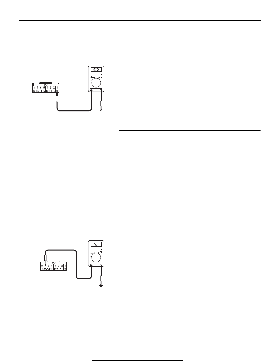
STEP 3. Check the ground circuit to the center panel unit. 
Measure the resistance at center panel unit connector 
C-104.
(1) Disconnect the connector, and measure at the wiring 

harness side.

(2) Measure resistance between terminal 9 and ground.

OK: The resistance should be 2 ohm or less.

Q: Is the measured resistance 2 ohms or less?

YES : Go to Step 5.
NO :  Go to Step 4.

STEP 4. Check the wiring harness between center panel 
unit connector C-104 (terminal 9) and ground.

• Check the ground wire for open circuit.

Q: Is the wiring harness between center panel unit 

connector C-104 (terminal 9) and ground in good 
condition?
YES : 
Check the trouble symptom.
NO :  The wiring harness may be damaged or the 

connector(s) may have loose, corroded or damaged 
terminals, or terminals pushed back in the connector. 
Repair the wiring harness as necessary.

STEP 5. Check the power supply circuit to the center panel 
unit. Measure the voltage at center panel unit connector 
C-104.
(1) Disconnect the connector, and measure at the harness side 

connector.

(2) Measure voltage between terminal 7 and ground.

OK: The voltage should measure approximately 12 
volts (battery positive voltage).

Q: Is the measured voltage approximately 12 volts (battery 

positive voltage)?
YES : 
Go to Step 7.
NO :  Go to Step 6.

AC709322 CT

Harness side: C-104

AC709325 BE

Harness side: C-104

RADIO AND CD PLAYER

TSB Revision

CHASSIS ELECTRICAL

54A-402

STEP 6. Check the wiring harness between center panel 
unit connector C-104 (terminal 7) and fusible link (36).

• Check the power supply line for open circuit and short cir-

cuit.

NOTE: Also ETACS-ECU connector C-307, C-317 for loose, 
corroded, or damaged terminals, or terminals pushed back in 
the connector. If joint connector ETACS-ECU connector C-307, 
C-317 are damaged, repair or replace the connector as 
described in GROUP 00E, Harness Connector Inspection 

P.00E-2

.

Q: Is the wiring harness between center panel unit 

connector C-104 (terminal 7) and fusible link (36) in 
good condition?
YES : 
Check the trouble symptom.
NO :  The wiring harness may be damaged or the 

connector(s) may have loose, corroded or damaged 
terminals, or terminals pushed back in the connector. 
Repair the wiring harness as necessary.

STEP 7. Replace the center panel unit temporarily, and 
check the trouble symptom.
Replace the center panel unit temporarily, and check that the 
audio works normally.
Q: Is the check result normal?

YES : Replace the center panel unit.
NO :  Replace the radio and CD player.

RADIO AND CD PLAYER

TSB Revision

CHASSIS ELECTRICAL

54A-403

INSPECTION PROCEDURE 5: Audio illuminations does not work normally.

CAUTION

Before replacing the radio and CD player, ensure that the power supply circuit, the ground circuit and 
the communication circuit are normal.

.

OPERATION

• When the position light is illuminated, the audio 

illumination is switched to the nighttime illumina-
tion.

• When the brightness is adjusted using the combi-

nation meter rheostat switch, the audio illumina-
tion brightness is also adjusted.

Center Panel Unit Communication Circuit

CENTER PANEL 
UNIT

AUDIO SWITCH PANEL

LCD PANEL (AUDIO)

A/C 
CONTROL 
PANEL

COMBINATION METER

RADIO AND CD PLAYER

ACA02653AC

Connector: C-03

AC709494

AP

Connectors: C-14, C-104, C-119

C-14

C-104

C-119

RADIO AND CD PLAYER

TSB Revision

CHASSIS ELECTRICAL

54A-404

.

COMMENTS ON TROUBLE SYMPTOM

The center panel unit, radio and CD player, combina-
tion meter, or communication line from the radio and 
CD player to the combination meter may have a 
problem.

.

PROBABLE CAUSES

• The combination meter may be defective.

• The radio and CD player may be defective.

• The center panel unit may be defective.

• Damaged harness wires and connectors

DIAGNOSIS

Required Special Tools:

• MB991223: Harness Set

• MB992006: Extra Fine Probe

STEP 1. Operation check of the center panel unit
Operate the audio control switch of the center panel unit, and 
check if the audio operates normally.
Q: Is the check result normal?

YES : Go to Step 2.
NO :  Refer to Inspection Procedure 4 "The audio does not 

operate normally by operating the radio and CD 
player of the center panel unit." 

P.54A-399

.

STEP 2. Check the combination meter.
Check whether the combination meter works normally.
Q: Is the check result normal?

YES : Go to Step 3.
NO :  Diagnose the combination meter (Refer to 

P.54A-34

).


Content   ..  99  100  101  102   ..