Mitsubishi Outlander (2013+). Manual - part 614
 

  Index      Mitsubishi     Mitsubishi Outlander - service repair manual 2013 year


Search            


Content   ..  612  613  614  615   ..


Mitsubishi Outlander (2013+). Manual - part 614


TROUBLESHOOTING

SUPPLEMENTAL RESTRAINT SYSTEM (SRS)

52B-107

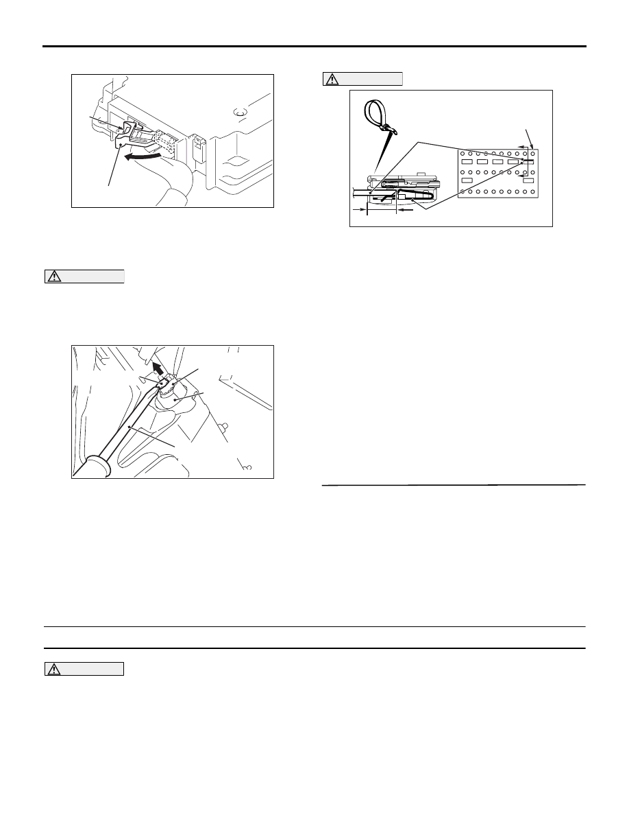
connected, disconnect it.

AC905015

A

AC

Lock lever

(2) While pushing the part "A" indicated in the figure 

of the harness side connector, turn the lock lever 
to the direction of the arrow to release the lock 
lever, and disconnect the SRS-ECU connector.

DANGER

To release the SRS-ECU connector short 
spring in the following operations, discon-
nect this harness side connector, and keep 
the squib circuit shorted.

AC609126AF

Locking button

Flat-tipped
screwdriver

Inflator

Harness side
connector

(3) Use the flat-tipped screwdriver to pull out the 

locking button of harness side connector. After 
releasing the lock, disconnect the knee air bag 

module harness side connector. 

AC905150 AR

A

A

Harness side
connector (front view)

Section
A - A

Cable tie

Short spring

4 mm or more

Terminal

CAUTION

The short spring may not be released due to the 
insufficient insertion. Therefore, insert the insu-
lator for 4 mm or more.
(4) Insert an insulator (width: 3 mm, thickness: 0.5 

mm) such as cable tie between the KDS-, KDS+ 
line and the short spring, and release the short 
spring.

(5) Take the measurements below at the SRS-ECU 

harness side connector.

• Continuity between KDS-, KDS+ line and 

body earth

OK: No continuity

Q: Is the check result normal?

YES : 

Go to Step 5.

NO : 

Repair the wiring harness KDS-, KDS+ line 
between the SRS-ECU connector and the 
knee air bag module connector.

STEP 5. Check whether the diagnosis code is 
reset.

Q: Is the diagnosis code No. B1633 set?

YES : 

Replace SRS-ECU (Refer to 

P.52B-129

).

NO : 

Intermittent malfunction (Refer to GROUP 
00 

− How to Use 

Troubleshooting/Inspection Service Points 

− 

How to Cope with Intermittent Malfunction ).

 Code No.B1634 Driver's knee air bag module (squib) system (shorted to squib circuit power supply)

CAUTION

If the diagnosis code B1634 is set to SRS-ECU, 
be sure to diagnose the CAN bus line.

OPERATION

Only when the frontal impact exceeding the threshold 
is simultaneously detected (turned ON) by the front 
impact sensor as well as by the analogue G-sensor 
in SRS-ECU, the electric current is supplied from 

SRS-ECU to the knee air bag module (squib).

TROUBLE JUDGEMENT

The code is set when the SRS-ECU driver's knee air 
bag module (squib) circuit is shorted to power supply.

PROBABLE CAUSES

• Poor contact of connector

TROUBLESHOOTING

SUPPLEMENTAL RESTRAINT SYSTEM (SRS)

52B-108

• Driver's knee air bag module (squib) harness 

shorted to power supply

• Malfunction of SRS-ECU

DIAGNOSIS PROCEDURE

STEP 1. M.U.T.-III CAN bus diagnostics.
Use M.U.T.-III to diagnose the CAN bus lines.

Q: Is the check result normal?

YES : 

Go to Step 2.

NO : 

Repair the CAN bus line (Refer to GROUP 
54C 

− Troubleshooting ).

STEP 2. Check whether the diagnosis code is 
reset.
(1) Connect the negative battery terminal.
(2) After erasing the diagnosis code memory, check 

the diagnosis code again.

(3) Disconnect the negative battery terminal.

Q: Is the diagnosis code No. B1634 set?

YES : 

Go to Step 3.

NO : 

Intermittent malfunction (Refer to GROUP 
00 

− How to Use 

Troubleshooting/Inspection Service Points 

− 

How to Cope with Intermittent Malfunction ).

STEP 3. Diagnosis check by dummy resistor 
connection.
(1) Check that the negative battery terminal is 

disconnected. If the negative battery terminal is 
connected, disconnect it.

AC609126AF

Locking button

Flat-tipped
screwdriver

Inflator

Harness side
connector

(2) Use the flat-tipped screwdriver to pull out the 

locking button of harness side connector. After 

releasing the lock, disconnect the knee air bag 
module harness side connector. 

AC301553DR

Harness side 
connector

MB991865

(Dummy resistor: 3    )

MB991884 

(Resistor harness)

(3) Connect dummy resistor (MB991865) to special 

tool resistor harness (MB991884).

(4) Connect the special tool resistor harness to the 

knee air bag module harness side connector.

(5) Connect the negative battery terminal.
(6) After erasing the diagnosis code memory, check 

the diagnosis code again.

(7) Disconnect the negative battery terminal.

Q: Is the diagnosis code No. B1634 set?

YES : 

Go to Step 4.

NO : 

Replace the driver’s knee air bag module 
(Refer to 

P.52B-139

).

STEP 4. Voltage measurement at the SRS-ECU 
connector.
(1) Check that the negative battery terminal is 

disconnected. If the negative battery terminal is 
connected, disconnect it.

AC905015

A

AC

Lock lever

(2) While pushing the part "A" indicated in the figure 

of the harness side connector, turn the lock lever 
to the direction of the arrow to release the lock 

TROUBLESHOOTING

SUPPLEMENTAL RESTRAINT SYSTEM (SRS)

52B-109

lever, and disconnect the SRS-ECU connector.

DANGER

To release the SRS-ECU connector short 
spring in the following operations, discon-
nect this harness side connector, and keep 
the squib circuit shorted.

AC609126AF

Locking button

Flat-tipped
screwdriver

Inflator

Harness side
connector

(3) Use the flat-tipped screwdriver to pull out the 

locking button of harness side connector. After 
releasing the lock, disconnect the knee air bag 
module harness side connector. 

AC905150 AR

A

A

Harness side
connector (front view)

Section
A - A

Cable tie

Short spring

4 mm or more

Terminal

CAUTION

The short spring may not be released due to the 
insufficient insertion. Therefore, insert the insu-
lator for 4 mm or more.
(4) Insert an insulator (width: 3 mm, thickness: 0.5 

mm) such as cable tie between the KDS-, KDS+ 
line and the short spring, and release the short 
spring.

(5) Connect the negative battery terminal.
(6) Ignition switch: ON
(7) Take the measurements below at the SRS-ECU 

harness side connector.

• Voltage between KDS-, KDS+ line and body 

earth

OK: 1 V or less

(8) Disconnect the negative battery terminal.

Q: Is the check result normal?

YES : 

Go to Step 5.

NO : 

Repair the wiring harness KDS-, KDS+ line 
between the SRS-ECU connector and the 
knee air bag module connector.

STEP 5. Check whether the diagnosis code is 
reset.

Q: Is the diagnosis code No. B1634 set?

YES : 

Replace SRS-ECU (Refer to 

P.52B-129

).

NO : 

Intermittent malfunction (Refer to GROUP 
00 

− How to Use 

Troubleshooting/Inspection Service Points 

− 

How to Cope with Intermittent Malfunction ).

Code No. B1646: Coding data mismatch

CAUTION

• If diagnosis code No. B1646 is set, diagnose 

the CAN bus lines.

• When replacing the ECU, always check that 

the communication circuit is normal.

FUNCTION

If a false coding data is written in the SRS-ECU, the 
SRS-ECU will set diagnosis code No. B1646.

TROUBLE JUDGEMENT

When correct coding data is not received from 
ETACS-ECU, SRS-ECU will determine that the a 
problem has occurred.

PROBABLE CAUSES

• Malfunction of CAN bus line

• Malfunction of ETACS-ECU

• Malfunction of SRS-ECU

TROUBLESHOOTING

SUPPLEMENTAL RESTRAINT SYSTEM (SRS)

52B-110

DIAGNOSIS PROCEDURE

1. M.U.T.-III CAN bus diagnostics

2. M.U.T.-III other system diagnosis code

3. Check whether the diagnosis code is reset.

Code No. B1647 Passenger's air bag ON indicator lamp (short circuited)

CAUTION

If the diagnosis code B1488 is set in the 
SRS-ECU, be sure to diagnose the CAN bus line

OPERATION

• Power for the passenger’s air bag ON indicator 

lamp is supplied from the fusible link (2).

• The passenger’s air bag ON indicator lamp illumi-

nates when the ignition switch is turned to the 
"ON" position and goes out after approximately 6 
to 8 seconds if there is not a malfunction in the 
SRS system.

TROUBLE JUDGEMENT

This code will be set if the passenger’s air bag ON 
indicator lamp driving circuit is short to earth.

PROBABLE CAUSES

• Damaged wiring harnesses or connectors

• Malfunction of the SRS-ECU

• Malfunction of the passenger’s air bag ON indica-

tor lamp

DIAGNOSIS PROCEDURE

STEP 1. M.U.T.-III CAN bus diagnostics.
Use M.U.T.-III to diagnose the CAN bus lines.

Q: Is the check result normal?

YES : 

Go to Step 2.

NO : 

Repair the CAN bus line (Refer to GROUP 
54C 

− Troubleshooting ).

STEP 2. Check whether the diagnosis code is 
reset.
(1) Connect the negative battery terminal.
(2) After erasing the diagnosis code memory, check 

the diagnosis code again.

(3) Disconnect the negative battery terminal.

Q: Is the diagnosis code No. B1647 set?

YES : 

Go to Step 3.

NO : 

Intermittent malfunction (Refer to GROUP 
00 

− How to Use 

Troubleshooting/Inspection Service Points 

− 

How to Cope with Intermittent Malfunction ).

STEP 3. Check the passenger’s air bag ON 
indicator lamp.
It is checked whether passenger’s air bag ON indica-
tor lamp is normal (Refer to 

P.52B-152

).

Q: Is the check result normal?

YES : 

Go to Step 4.

NO : 

Replace hazard indicator assembly (Refer 
to GROUP 52A 

− Instrument Panel 

Assembly ).

STEP 4. Resistance measurement at the 
SRS-ECU connector.
(1) Check that the negative battery terminal is 

disconnected. If the negative battery terminal is 
connected, disconnect it.

AC905015

A

AC

Lock lever

(2) While pushing the part "A" indicated in the figure 

of the harness side connector, turn the lock lever 
to the direction of the arrow to release the lock 
lever, and disconnect the SRS-ECU connector.

(3) Disconnect the hazard indicator assembly 

connector.

(4) Take the measurements below at the SRS-ECU 

connector. 

• Continuity between ONLP line and body earth

OK: No continuity

Q: Is the check result normal?

YES : 

Go to Step 5.

NO : 

Repair the wiring harnesses ONLP line 
between the SRS-ECU connector and the 
hazard indicator assembly connector.

STEP 5. Resistance measurement at the hazard 
indicator assembly connector.
(1) Check that the negative battery terminal is 


Content   ..  612  613  614  615   ..