Mitsubishi Outlander (2013+). Manual - part 574
Rear wiper motor removal steps
4.
Cover
>>
B
<<
5.
Rear wiper arm assembly
•
Tailgate trim (Refer to GROUP 52A,
Tailgate Trim )
6.
Grommet
7.
Rear wiper motor assembly
8.
Rear wiper motor bracket
Rear washer hose removal steps
•
Front/rear scuff plate, cowl side
trim, quarter trim (Refer to GROUP
52A, Interior Trim )
•
Tailgate trim (Refer to GROUP 52A,
Tailgate Trim )
9.
Rear washer hose
REAR WIPER AND WASHER
EXTERIOR
51-55
NOTE: For removal and installation of the wiper and
washer switch, refer to GROUP 54A, Column Switch
.
INSTALLATION SERVICE POINTS
>>A<< REAR WIPER BLADE INSTALLA-
TION
AC101090
AE
A
A
Wiper blade
Backing
Backing
Section A – A
Wiper
blade
Backing
CAUTION
Use a curved backing like that shown for the
backing of a wiper blade to ensure sustained
wiper wiping performance.
>>B<< REAR WIPER ARM AND BLADE
ASSEMBLY INSTALLATION
ACB05700 AB
Rear wiper arm and
blade assembly
(A)
Assemble the wiper blade so that their edge stops at
the specified position.
Standard value:
(A):
φ 2 marking ± 5 mm
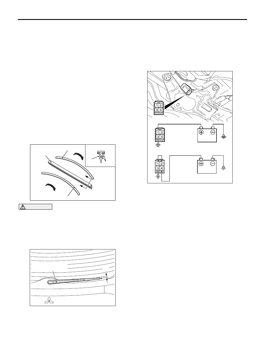
INSPECTION
M1511019103696
REAR WIPER MOTOR CHECK
AC103246
AC506678
AB
Operation check
Stop position check
Inspect the rear wiper motor by disconnecting the
harness connector with the motor attached to the
vehicle.
REAR WIPER MOTOR OPERATION
CHECK
Connect the battery to the rear wiper motor to
inspect the motor operation as shown in the illustra-
tion.
REAR WIPER MOTOR STOP POSITION
CHECK
1. Connect the battery to the rear wiper motor as
shown in the illustration.
2. Disconnect the battery in the middle of the motor
rotation and check to see that the motor stops.
3. Reconnect the battery.
4. Check to see that the rear wiper motor runs and
then stops at the automatic stop position.