Mitsubishi Outlander (2003+). Manual - part 27
 

  Index      Mitsubishi     Mitsubishi Outlander - service repair manual 2003 year


Search            


Content   ..  25  26  27  28   ..


Mitsubishi Outlander (2003+). Manual - part 27


CYLINDER HEAD GASKET

ENGINE MECHANICAL <4G69>

11C-35

CAUTION

The bolt is not tightening sufficiently if the 
tightening angle is less than a 90 degree 
angle.

If the tightening angle exceeds the standard 
specification, remove the bolt and start over 
from step 1.

(5) Tighten in a 90 degree angle as shown in the 

instructions of the figure, then check to see 
that the paint mark on the head of the cylinder 
head bolts and the paint mark on the cylinder 
head is on a linear line.

>>C<< FUEL HIGH-PRESSURE HOSE 
INSTALLATION

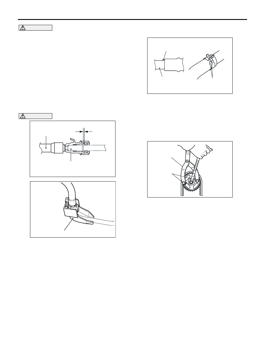
CAUTION

After connecting the fuel high-pressure hose, 
slightly pull it to ensure that it is installed 
securely. Also confirm that there is a play 
approximately 3 mm. Then install the stopper 
securely.
Apply a small amount of engine oil to the fuel line 
pipe and then install the fuel high-pressure hose.

>>D<< RADIATOR UPPER HOSE CONNECTION

1. Insert radiator upper hose until it contacts the 

projection on the water outlet fitting.

2. Align the mating marks on the radiator upper hose 

and hose clamp, and then secure the radiator 
upper hose.

>>E<< CAMSHAFT SPROCKET INSTALLATION

1. Use the following special tool as during removal to 

hold the camshaft sprocket.

Front hub and flange yoke holder (MB990767)

Pin (MD998719)

2. Tighten the camshaft sprocket mounting bolt to 

the specified torque.

Tightening torque: 89 

±

 9 N

m

AC301864AB

3 mm

Fuel 
high-pressure 
hose

Fuel line pipe
(Engine oil applied)

AC304583

AB

Stopper

AC200642

Mating marks

Projection

Water outlet fitting

AB

AC100302

MD998719

MB990767

AB

TIMING BELT

ENGINE MECHANICAL <4G69>

11C-36

TIMING BELT

REMOVAL AND INSTALLATION

M1112004300827

Pre-removal Operation

Under Cover Removal (Refer to GROUP 51, Under Cover 

P.51-19

).

Crankshaft Shaft Damper Pulley Removal (Refer to 

P.11C-17

).

Post-installation Operation

Crankshaft Shaft Damper Pulley Installation (Refer to 

P.11C-17

).

Drive Belt Tension Check (Refer to 

P.11C-8

).

Under Cover Installation (Refer to GROUP 51, Under 

Cove

P.51-19

).

AC308981AB

14 ± 1 N·m

1

13

12

10

9

8

7

6

5

11

4

3

2

14 ± 1 N·m

8.8 ± 1.0 N·m

44 ± 10 N·m

22 ± 4 N·m

11 ± 1 N·m

9.0 ± 1.0 N·m

11 ± 1 N·m

79 ± 5 N·m

11 ± 1 N·m

21 ± 4 N·m

48 ± 5 N·m

23 ± 3 N·m

14 ± 3 N·m

Removal steps

1.

Control wiring harness connection 

2.

Battery wiring harness connection 

3.

Connector bracket

Engine front mounting bracket 
(Refer to GROUP 32, Engine 
Mount 

P.32-5

).

4.

Harness bracket

5.

Timing belt upper cover

6.

Water pump pulley

7.

Idler pulley

8.

Auto-tensioner

9.

Timing belt lower cover 

>>G<<

Valve timing belt tension 
adjustment (Installation only)

<<A>>

>>F<<

10. Valve timing belt 

>>E<<

11. Timing belt tensioner pulley
12. Timing belt tensioner arm

>>D<<

13. Timing belt tensioner adjuster

Removal steps (Continued)

TIMING BELT

ENGINE MECHANICAL <4G69>

11C-37

AC308982

19

18

17

16

15

14

22

20

21

(Engine oil)

35 ± 6 N·m

8.5 ± 0.5 N·m

19 ± 3 N·m

167 N·m

AB

Removal steps

14. Timing belt Idler pulley
15. Timing belt lower cover bracket
16. Crank angle sensor

<<B>>

>>C<<

17. Crankshaft pulley centre bolt

<<B>>

>>C<<

18. Crankshaft pulley washer

<<B>>

>>C<<

19. Crankshaft camshaft drive sprocket

>>C<<

20. Crankshaft angle sensing blade

>>B<<

Balancer timing belt tension 
adjustment (Installation only)

>>A<<

21. Balancer timing belt tensioner

<<C>>

>>A<<

22. Balancer timing belt 

Removal steps (Continued)

TIMING BELT

ENGINE MECHANICAL <4G69>

11C-38

REMOVAL SERVICE POINTS

<<A>> VALVE TIMING BELT REMOVAL

CAUTION

Never turn the crankshaft anti-clockwise.

1. Turn the crankshaft clockwise, align each timing 

mark to set No.1 cylinder to TDC of its 
compression stroke.

2. Remove the timing belt under cover rubber plug 

and then set special tool adjusting bolt 
(MD998738).

3. Screw in the special tool with hands until it 

contacts the timing belt tensioner arm.

CAUTION

The special tool can be gradually installed at a 
rate of a 30 degree turn per second. If it is 
screwed in all at once, the timing belt tensioner 
adjuster rod will not easily retract and the special 
tool may bend.

4. Gradually screw in the special tool and then align 

the timing belt tensioner adjuster rod set hole A 
with the timing belt tensioner adjuster cylinder set 
hole B.

AC301866

AB

Timing mark

Crankshaft
camshaft
drive sprocket

Camshaft
sprocket

Timing mark

Timing mark

Engine oil pump 
sprocket

AC301452AB

MD998738

Timing belt
under cover

AC301373

AB

MD998738

Timing belt
tensioner arm

AC301856

A

B

AB


Content   ..  25  26  27  28   ..