Mitsubishi Outlander (2003+). Manual - part 25
 

  Index      Mitsubishi     Mitsubishi Outlander - service repair manual 2003 year


Search            


Content   ..  23  24  25  26   ..


Mitsubishi Outlander (2003+). Manual - part 25


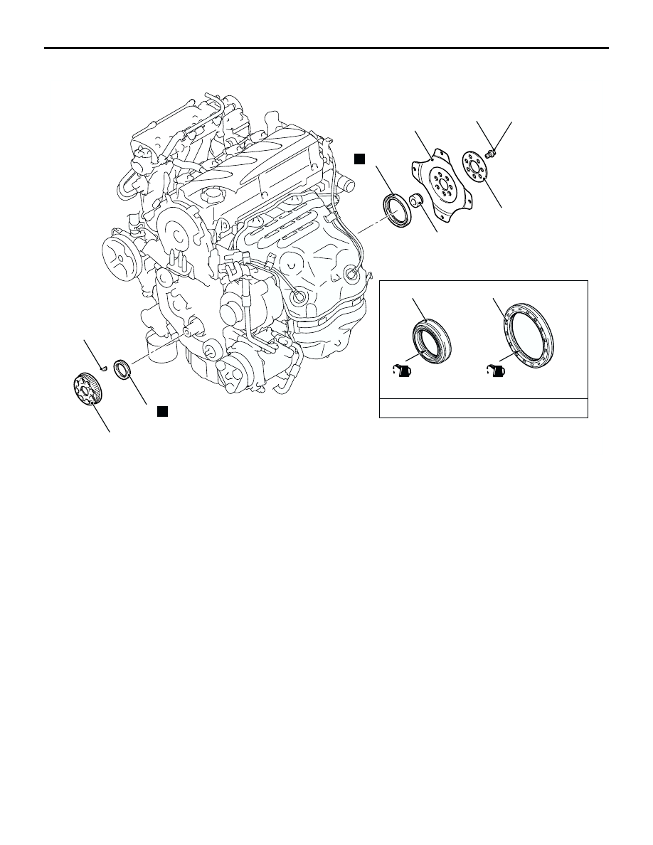
CRANKSHAFT OIL SEAL

ENGINE MECHANICAL <4G69>

11C-27

<A/T>

AC308978

1

2

N

8

7

6

4

N

132 ± 5 N·m

(Lip section)

Engine oil

AB

(Lip section)

3

8

 5

Crankshaft front oil seal removal 
steps

Valve timing belt, balancer timing 
belt (Refer to 

P.11C-36

).

>>D<<

1.

Crankshaft balancer shaft drive 
sprocket

2.

Crankshaft key

>>C<<

3.

Crankshaft front oil seal

Crankshaft rear oil seal removal 
steps

Transmission assembly (Refer to 
GROUP 23A, Transmission 
Assembly 

P.23A-172

).

<<B>>

>>B<<

4.

A/T drive plate bolts

5.

A/T drive plate adapter plate

6.

A/T drive plate 

7.

Crankshaft bush

>>A<<

8.

Crankshaft rear oil seal

CRANKSHAFT OIL SEAL

ENGINE MECHANICAL <4G69>

11C-28

REMOVAL SERVICE POINTS

<<A>> TRANSMISSION ASSEMBLY REMOVAL

CAUTION

Do not remove the flywheel bolt shown by the 
arrow. If this bolt is removed, the flywheel 
assembly will become out of balance and 
damaged.
Refer to GROUP 22A, Transmission Assembly 

P.22A-15

.

<<B>> FLYWHEEL BOLTS/A/T DRIVE PLATE 
BOLTS REMOVAL

1. Use special tool flywheel stopper (MD998781) to 

secure the flywheel assembly or A/T drive plate.

2. Remove the flywheel bolts or A/T drive plate bolts.

INSTALLATION SERVICE POINTS

>>A<< CRANKSHAFT REAR OIL SEAL 
INSTALLATION

1. Apply a small amount of engine oil to the entire 

inner diameter of the oil seal lip.

2. Use the following special tools to press-fit the oil 

seal.

Installer bar (MB990938)

Crankshaft rear oil seal installer (MD998776)

>>B<< FLYWHEEL BOLTS/A/T DRIVE PLATE 
BOLTS INSTALLATION

1. Use special tool flywheel stopper (MD998781) to 

secure the flywheel assembly or A/T drive plate in 
the same manner as removal.

2. Tighten the flywheel bolts or A/T drive plate bolts 

to the specified torque.

Tightening torque: 132 

±

 5 N

m

>>C<< CRANKSHAFT FRONT OIL SEAL 
INSTALLATION

1. Apply a small amount of engine oil to the outer 

diameter of special tool crankshaft front oil seal 
guide (MD998285) and install it to the crankshaft.

2. Apply a small amount of engine oil to the entire 

inner diameter of the oil seal lip.

3. Use special tool crankshaft front oil seal installer 

(MD998375) to press-fit the oil seal.

AC300897

AC308604

Flywheel 
bolt

Engine front

AB

Flywheel 
assembly

AC301854AB

MD998781

AC102328 AB

Oil seal

MB990938

MD998776

Crankshaft

(Engine oil)

AC301855AB

MD998781

AC102329AC

MD998285

(Engine oil)

(Oil applied to the
circumference)

Oil seal

Crankshaft

MD998375

CRANKSHAFT OIL SEAL

ENGINE MECHANICAL <4G69>

11C-29

>>D<< CRANKSHAFT BALANCER SHAFT DRIVE 
SPROCKET INSTALLATION

1. Clean or degrease the front case, the crankshaft 

and the crankshaft balancer shaft drive sprocket 
as shown.
NOTE: Also clean the degreased surfaces.

2. Install the crankshaft balancer shaft drive sprocket 

in the direction shown in the illustration.

AC301346

AB

: Clean
: Clean and degrease

Crankshaft
balancershaft
drive sprocket

Engine front

Front case

Crankshaft

CYLINDER HEAD GASKET

ENGINE MECHANICAL <4G69>

11C-30

CYLINDER HEAD GASKET

REMOVAL AND INSTALLATION

M1112004000848

Pre-removal Operation

Fuel Line Pressure Reduction [Refer to GROUP 13B, 

On-vehicle Service 

 Fuel Pump Connector 

Disconnection (How to Reduce Pressurized Fuel Lines) 

P.13B-428

].

Engine Coolant Draining (Refer to GROUP 14, On-vehicle 

Service 

 Engine Coolant Replacement 

P.14-17

).

Air Cleaner Removal (Refer to GROUP 15, Air Cleaner 

P.15-4

).

Accelerator Cable Removal (Refer to GROUP 17, 

Accelerator Cable and Peda

P.17-7

).

Post-installation Operation

Accelerator Cable Installation (Refer to GROUP 17, 

Accelerator Cable and Pedal 

P.17-7

).

Air Cleaner Installation (Refer to GROUP 15, Air Cleaner 

P.15-4

).

Engine Coolant Refilling (Refer to GROUP 14, On-vehicle 

Service 

 Engine Coolant Replacement 

P.14-17

).

Accelerator Cable Adjustment (Refer to GROUP 17, 

On-vehicle Service 

 Accelerator Cable Check and 

Adjustment 

P.17-5

).

Fuel Leak Check

AC308979

N

(Engine oil)

13 ± 1 N·m

14 ± 3 N·m

9.0 ± 2.0 N·m

5.0 ± 1.0 N·m

1

6

5

4

3

2

AB

7

Removal steps

1.

Control wiring harness connection 

2.

Battery wiring harness connection 

3.

Radiator lower hose clamp

4.

Canister vacuum hose connection

5.

Brake booster vacuum hose 
connection

6.

Engine oil level gauge and guide 
assembly

7.

O-ring

Removal steps (Continued)


Content   ..  23  24  25  26   ..