Mitsubishi Montero (2004+). Manual - part 101
 

  Index      Mitsubishi     Mitsubishi Montero - service repair manual 2004 year


Search            


Content   ..  99  100  101  102   ..


Mitsubishi Montero (2004+). Manual - part 101


ON-VEHICLE SERVICE

TSB Revision

ENGINE MECHANICAL

11A-9

CAUTION

To prevent damage to scan tool MB991958, always turn the 
ignition switch to the "LOCK" (OFF) position before con-
necting or disconnecting scan tool MB991958.
2. Connect scan tool MB991958 to the data link connector.
3. Check the basic ignition timing.

Standard value: 5

° BTDC ± 3°

4. Start the engine.
5. Run the engine at idle for 2 minutes.
6. Check the idle speed. Select item number 22 and take a 

reading of the idle speed.

Curb idle speed: 700 

± 100 r/min

NOTE: The idle speed is controlled automatically by the idle 
air control system.

7. If the idle speed is outside the standard value, refer to 

GROUP 13A, Multiport Fuel Injection (MFI) 

− Multiport Fuel 

Injection (MFI) Diagnosis 

− Symptom Chart 

P.13A-30

.

IDLE MIXTURE CHECK

M1111002100352

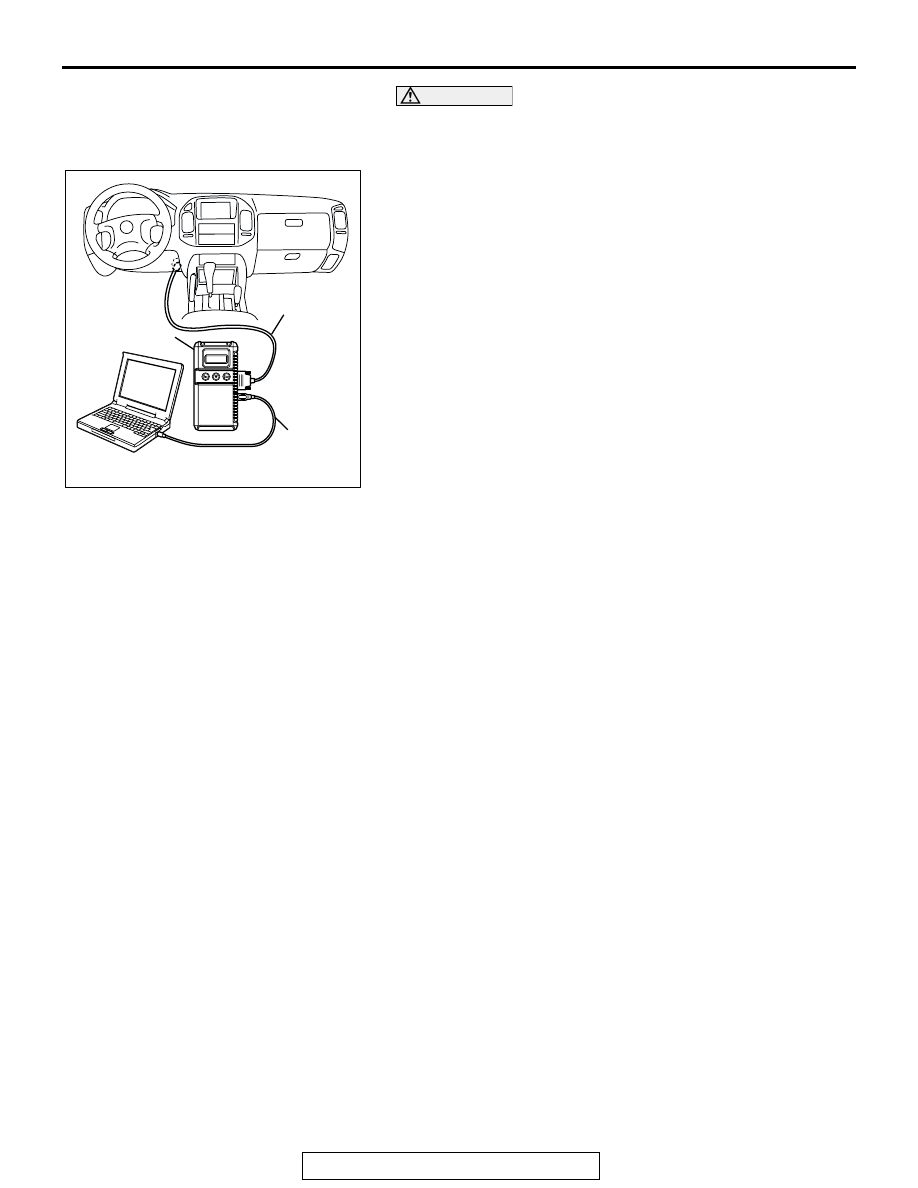
Required Special Tool:
MB991958: Scan Tool (MUT-III Sub Assembly)

• MB991824: V.C.I.

• MB991827: MUT-III USB Cable

• MB991911: MUT-III Main Harness B

1. Before checks, set the vehicle in the following condition:

• Engine coolant temperature: 80 − 95°C (176 − 203°F)

• Lights and all accessories: OFF

• Transmission: P range

NOTE: Vehicles for Canada, the headlight, taillight, etc. 
remain lit even when the lighting switch is in "OFF" position 
but this is no problem for checks.

AK302970

AB

MB991911

MB991824

MB991827

ON-VEHICLE SERVICE

TSB Revision

ENGINE MECHANICAL

11A-10

CAUTION

To prevent damage to scan tool MB991958, always turn the 
ignition switch to the "LOCK" (OFF) position before con-
necting or disconnecting scan tool MB991958.
2. Connect scan tool MB991958 to the data link connector.
3. Check that the basic ignition timing is within the standard 

value. 

Standard value: 5

° BTDC ± 3°

4. Start the engine and increase the engine speed to 2,500 

r/min for 2 minutes.

5. Set the CO, HC tester.
6. Check the CO contents and the HC contents at idle.

Standard value:

CO contents: 0.5% or less
HC contents: 100 ppm or less

7. If the CO and HC contents do not remain inside the standard 

value, check the following items:
NOTE: Replace the catalytic converter when the CO and HC 
contents do not remain inside the standard value, even 
though the result of the inspection is normal for all items.

• Diagnostic output

• Closed-loop control (When the closed-loop control is carried 

out normally, the output signal of the heated oxygen sensor 
changes between 0 

− 400 mV and 600 − 1,000 mV at idle.)

• Fuel pressures

• Injector

• Ignition coil, spark plug cable, spark plug

• Exhaust gas recirculation system and EGR valve leak

• Evaporative emission system

• Compression pressure

COMPRESSION PRESSURE CHECK

M1111002600540

1. Before checks, check that the engine oil, starter and battery 

are normal. Also, set the vehicle in the following condition:

• Engine coolant temperature: 80 − 95°C (176 − 203°F)

• Lights and all accessories: OFF

• Transmission: P range

NOTE: Vehicles for Canada, the headlight, taillight, etc. 
remain lit even when the lighting switch is in "OFF" position 
but this is no problem for checks.

2. Disconnect the spark plug cables.
3. Remove all of the spark plugs.

AK302970

AB

MB991911

MB991824

MB991827

ON-VEHICLE SERVICE

TSB Revision

ENGINE MECHANICAL

11A-11

4. Disconnect the crankshaft position sensor connector.

NOTE:  Doing this will prevent the engine control module 
from carrying out ignition and fuel injection.

WARNING

Keep your distance from the spark plug hole when 
cranking. Oil, fuel, etc., may spray out from the spark 
plug hole and may cause serious injury.

5. Cover the spark plug hole with a shop towel etc., during 

cranking. After the engine has been cranked, check for 
foreign material adhering to the shop towel.

6. Set compression gauge to one of the spark plug holes.
7. Crank the engine with the throttle valve fully open and 

measure the compression pressure.

Standard value (at engine speed of 250 

 400 r/min): 

1,548 kPa (225 psi)
Minimum limit (at engine speed of 250 

 400 r/min): 

1,117 kPa (162 psi)

8. Measure the compression pressure for all the cylinders, and 

check that the pressure differences of the cylinders are 
below the limit.

Limit: 98 kPa (14 psi)

9. If there is a cylinder with compression or a compression 

difference that is outside the limit, pour a small amount of 
engine oil through the spark plug hole, and repeat the 
operations in steps 6 to 8.

(1) If the compression increases after oil is added, the cause 

of the malfunction is a worn or damaged piston ring 
and/or cylinder inner surface.

(2) If the compression does not rise after oil is added, the 

cause is a burnt or defective valve seat, or pressure is 
leaking from the gasket.

10.Connect the crankshaft position sensor connector.
11.Install the spark plugs and spark plug cables.
12.Use the scan tool to erase the diagnostic trouble codes.

NOTE: This will erase the diagnostic trouble code resulting 
from the crankshaft position sensor connector being discon-
nected.

MANIFOLD VACUUM CHECK

M1111002700495

1. Start the engine and allow it to warm up until the 

temperature of the engine coolant reaches 80 

− 95°C (176 − 

203

°F).

2. Connect an engine tachometer.

AK200795 AB

CRANKSHAFT
POSITION
SENSOR
CONNECTOR

AKX00436

COMPRESSION
GAUGE

AB

ON-VEHICLE SERVICE

TSB Revision

ENGINE MECHANICAL

11A-12

3. Attach a tee-fitting union to the vacuum hose between the 

fuel pressure regulator and the intake manifold plenum, and 
connect a vacuum gauge.

4. Start the engine and check that idle speed is within 

specification. Then check the vacuum gauge reading.

Idle speed: 700 

± 100 r/min

Minimum limit: 60 kPa (18 in Hg)

LASH ADJUSTER CHECK

M1111002900411

If an abnormal noise (chattering noise) suspected to be caused 
by malfunction of the lash adjuster is produced immediately 
after starting the engine and does not disappear, perform the 
following check.
NOTE: An abnormal noise due to malfunction of the lash 
adjuster is produced immediately after starting the engine and 
changes with the engine speed, irrespective of the engine load.
If, the abnormal noise is not produced immediately after start-
ing the engine or does not change with the engine speed, or it 
changes with the engine load, the lash adjuster is not the cause 
for the abnormal noise.
NOTE: When the lash adjuster is malfunctioning, the abnormal 
noise is rarely eliminated by continuing the warming-up of the 
engine at idle speed.
However, the abnormal noise may disappear only when seizure 
is caused by oil sludge in the engine whose oil is not main-
tained properly.
1. Start the engine.
2. Check if the abnormal noise produced immediately after 

starting the engine, changes with the change in the engine 
speed.
If the abnormal noise is not produced immediately after 
starting the engine or it does not change with the engine 
speed, the lash adjuster is not the cause for the noise. 
Therefore, investigate other causes. The abnormal noise is 
probably caused by some other parts than the engine proper 
if it does not change with the engine speed. (In this case, the 
lash adjuster is in good condition.)

3. With the engine idling, change the engine load (shift from N 

to D range, for example) to make sure that there is no 
change in the level of abnormal noise.
If there is a change in the level of abnormal noise, suspect a 
tapping noise due to worn crankshaft bearing or connecting 
rod bearing (In this case, the lash adjuster is in good 
condition.).

4. After completion of warm-up, run the engine at idle to check 

for abnormal noise.

AK200796

VACUUM GAUGE

AK200796AB


Content   ..  99  100  101  102   ..