Mitsubishi Montero (2002-2004). Manual - part 380
INPUT SIGNAL PROCEDURES
TSB Revision
SWS INPUT SIGNAL PROCEDURES
54Bc-67
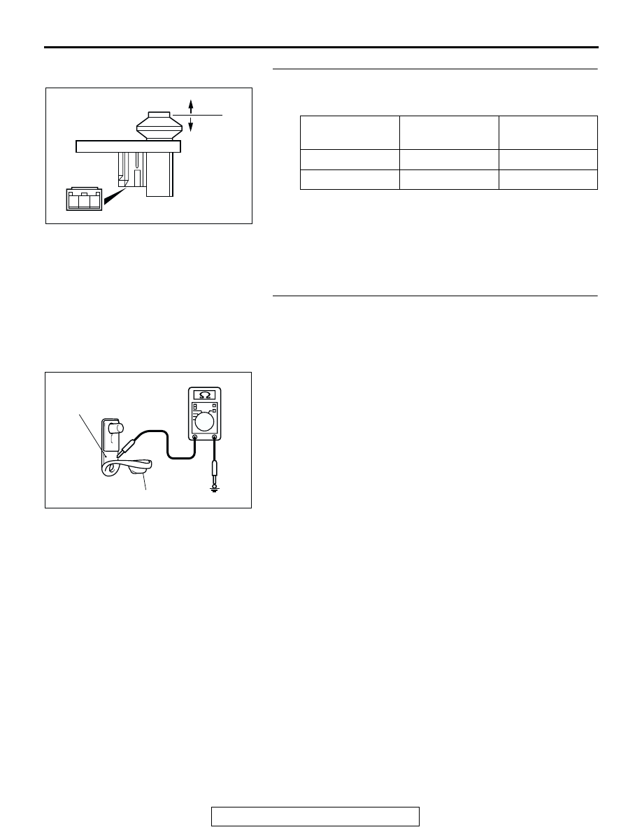
STEP 6. Check the rear door switch (RH).
Remove the rear door switch (RH). Then check continuity
between the switch terminals and the switch body.
Q: Is the rear door switch (RH) in good condition?
YES : Go to Step 7.
NO : Replace the rear door switch (RH). If the functions,
which are described in "CIRCUIT OPERATION", work
normally, the input signal from the rear door switch
(RH) should be normal.
STEP 7. Measure at the lower metal part of the rear door
switch (RH) in order to check the ground circuit to the rear
door switch (RH).
NOTE: Check that the rear door switch (RH) is grounded to the
vehicle body by means of its mounting screw.
Remove the cap, and measure the resistance value between
the lower metal part and the ground.
• The resistance should equal 2 ohms or less.
Q: Is the measured resistance 2 ohms or less?
YES : Go to Step 8.
NO : Check the fit of the switch, and repair if necessary. If
the functions, which are described in "CIRCUIT
OPERATION", work normally, the input signal from
the rear door switch (RH) should be normal.
SWITCH
POSITION
TESTER
CONNECTION
SPECIFIED
CONDITION
Released (ON)
2
− switch body
Less than 2 ohms
Depressed (OFF) 2
− switch body
Open circuit
1 2 3
ACX01865 AC
ON
OFF
ACX01600AB
METAL PART
CUP