Mitsubishi Montero (2002-2004). Manual - part 379
 

  Index      Mitsubishi     Mitsubishi Montero - service repair manual 2002-2004 year


Search            


Content   ..  377  378  379  380   ..


Mitsubishi Montero (2002-2004). Manual - part 379


INPUT SIGNAL PROCEDURES

TSB Revision

SWS INPUT SIGNAL PROCEDURES

54Bc-63

.

CIRCUIT OPERATION
The ETACS-ECU operates the following functions or 
systems according to signal from the driver's or front 
passenger's, rear or back door switches:

• Light reminder tone alarm function <Driver’s door 

switch>

• Power window timer function <Driver’s, front pas-

senger’s door switch>

• Headlight automatic shutdown function <Driver’s 

door switch>

• Keyless entry system <All door switches>

• Dome light <All door switches>

.

TECHNICAL DESCRIPTION (COMMENT)
If the signal is not normal, the functions or systems, 
which are described in "CIRCUIT OPERATION", do 
not work normally. If the signal is not normal, the 
driver's, front passenger's, rear or back door switch 
or the ETACS-ECU may be defective.

.

TROUBLESHOOTING HINTS

• The driver's, front passenger's, rear or back door 

switch may be defective

• The ETACS-ECU may be defective

• The wiring harness or connectors may have 

loose, corroded, or damaged terminals, or termi-
nals pushed back in the connector

DIAGNOSIS

Required Special Tools:

• MB991223: Harness Set

• MB991502: Scan Tool (MUT-II)

STEP 1. Verify which door switch is defective.
Q: Which door switch signal is not entered?

Driver's or front passenger's door : Refer to Inspection 

Procedure O-5 "ETACS-ECU does not receive any 
signal from the driver's or the front passenger's door 
switch 

P.54Bc-23

."

Rear door (LH) : Go to Step 2.
Rear door (RH) : Go to Step 6.
Back door : Go to Step 10.
Driver’s, rear (LH) and back door : Go to Step 14.

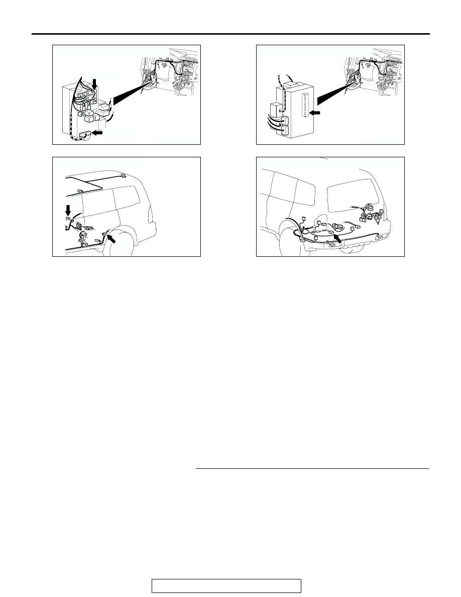
AC204173

CONNECTORS : D-209, 217

AK

D-209

D-217

AC204174

CONNECTOR : D-222            

AE

AC204178

CONNECTORS : F-05, F-09

F-05

F-09

AM

AC204179

CONNECTOR : G-15

AL

INPUT SIGNAL PROCEDURES

TSB Revision

SWS INPUT SIGNAL PROCEDURES

54Bc-64

STEP 2. Check the rear door switch (LH).
Remove the rear door switch (LH). Then check continuity 
between the switch terminals and the switch body.

Q: Is the rear door switch (LH) in good condition?

YES : Go to Step 3.
NO :  Replace the rear door switch (LH). If the functions, 

which are described in "CIRCUIT OPERATION", work 
normally, the input signal from the rear door switch 
(LH) should be normal.

STEP 3. Measure at the lower metal part of the rear door 
switch (LH) in order to check the ground circuit to the rear 
door switch (LH).
NOTE: Check that the rear door switch (LH) is grounded to the 
vehicle body by means of its mounting screw.
Remove the cap, and measure the resistance value between 
the lower metal part and the ground.

• The resistance should equal 2 ohms or less.

Q: Is the measured resistance 2 ohms or less?

YES : Go to Step 4.
NO :  Check the fit of the switch, and repair if necessary. If 

the functions, which are described in "CIRCUIT 
OPERATION", work normally, the input signal from 
the rear door switch (LH) should be normal.

SWITCH 
POSITION

TESTER 
CONNECTION

SPECIFIED 
CONDITION

Released (ON)

− switch body

Less than 2 ohms

Depressed (OFF) 2 

− switch body

Open circuit

1 2 3

ACX01865 AC

ON

OFF

ACX01600AB

METAL PART

CUP

INPUT SIGNAL PROCEDURES

TSB Revision

SWS INPUT SIGNAL PROCEDURES

54Bc-65

STEP 4. Check rear door switch (LH) connector F-09 and 
ETACS-ECU connector D-222 for loose, corroded or 
damaged terminals, or terminals pushed back in the 
connector.
Q: Are rear door switch (LH) connector F-09 and ETACS-

ECU connector D-222 in good condition?
YES : 
Go to Step 5.
NO :  Repair or replace the damaged component(s). Refer 

to GROUP 00E, Harness Connector Inspection 

P.00E-2

. If the functions, which are described in 

"CIRCUIT OPERATION", work normally, the input 
signal from the rear door switch (LH) should be 
normal.

AC204174

CONNECTOR : D-222

AB

1

2

3

5

6

4

9 8

121110

13

15 14

16

17

7

19

20

18

JUNCTION BLOCK SIDE

D-222

AC204178

CONNECTOR : F-09

AC

HARNESS SIDE

1

2

3

F-09

INPUT SIGNAL PROCEDURES

TSB Revision

SWS INPUT SIGNAL PROCEDURES

54Bc-66

STEP 5. Check the wiring harness between rear door 
switch (LH) connector F-09 (terminal 2) and ETACS-ECU 
connector D-222 (terminal 7).

NOTE: Also check intermediate connector D-125 and junction 
block connector D-217 for loose, corroded, or damaged termi-
nals, or terminals pushed back in the connector. If junction 
block connector D-217 or intermediate connector D-125 is 
damaged, Repair or replace the damaged component(s) as 
described in GROUP 00E, Harness Connector Inspection 

P.00E-2

.

Q: Is the wiring harness between rear door switch (LH) 

connector F-09 (terminal 2) and ETACS-ECU connector 
D-222 (terminal 7) in good condition?
YES : 
Replace the ETACS-ECU. If the functions, which are 

described in "CIRCUIT OPERATION", work normally, 
the input signal from the rear door switch (LH) should 
be normal.

NO :  The wiring harness may be damaged or the 

connector(s) may have loose, corroded or damaged 
terminals, or terminals pushed back in the connector. 
Repair the wiring harness as necessary. If the 
functions, which are described in "CIRCUIT 
OPERATION", work normally, the input signal from 
the rear door switch (LH) should be normal.

AC204174

CONNECTOR : D-222

AB

1

2

3

5

6

4

9 8

121110

13

15 14

16

17

7

19

20

18

JUNCTION BLOCK SIDE

D-222

AC204178

CONNECTOR : F-09

AC

HARNESS SIDE

1

2

3

F-09

AC204170

CONNECTOR : D-125

AO

9

8

6 7

5

3 4

20

32

21

33

43

17 18

30

41

16

29

28

39 40

13

25

12

24

35 36

14

26

37

15

27

38

19

31

42

1

10

22

2

11

23

34

AC204173

CONNECTOR : D-217

AG

HARNESS SIDE

8

1

11 10

3

4

12

9

2

13

14

6 5

15

7

D-217


Content   ..  377  378  379  380   ..