Mitsubishi Galant 9G. Manual - part 986


  Index      Mitsubishi     Mitsubishi Galant 9G - service repair manual


Search            


Content   ..  984  985  986  987   ..


Mitsubishi Galant 9G. Manual - part 986


MULTIPORT FUEL INJECTION (MFI) DIAGNOSIS

TSB Revision

MULTIPORT FUEL INJECTION (MFI) <3.8L ENGINE>

13B-244

DIAGNOSIS

Required Special Tools:

• MD998464: Test Harness

• MB991923: Power Plant ECU Check Harness

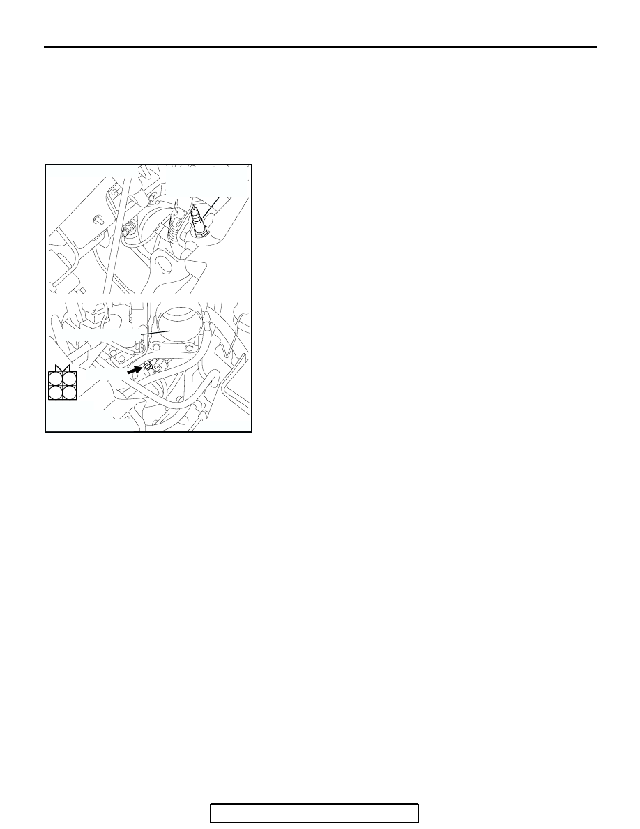
STEP 1. Check harness connector B-09 at the right bank 
heated oxygen sensor (front) for damage.

Q: Is the harness connector in good condition?

YES : Go to Step 2.
NO :  Repair or replace it. Refer to GROUP 00E, Harness 

Connector Inspection 

P.00E-2

. Then go to Step 12.

1

2

3

4

AK303048

B-09 (B)

CONNECTOR: B-09

THROTTLE BODY

RIGHT BANK
HEATED OXYGEN
SENSOR (FRONT)

AB

HARNESS
CONNECTOR:
COMPONENT SIDE

MULTIPORT FUEL INJECTION (MFI) DIAGNOSIS

TSB Revision

MULTIPORT FUEL INJECTION (MFI) <3.8L ENGINE>

13B-245

STEP 2. Check the right bank heated oxygen sensor 
(front).

(1) Disconnect right bank heated oxygen sensor (front) 

connector B-09 and connect test harness special tool, 
MD998464, to the connector on the right bank heated 
oxygen (front) sensor side.

(2) Measure the resistance between heated oxygen sensor 

connector terminal No. 1 (red clip) and terminal No. 3 (blue 
clip).

Standard value: 4.5 

 8.0 ohms [at 20°C (68°F)]

Q: Is the measured resistance between 4.5 and 8.0 ohms 

[at 20

°C (68°F)]?

YES : Go to Step 3.
NO :  Replace the right bank heated oxygen sensor (front). 

Then go to Step 12.

1

2

3

4

AK303048

B-09 (B)

CONNECTOR: B-09

THROTTLE BODY

RIGHT BANK
HEATED OXYGEN
SENSOR (FRONT)

AB

HARNESS
CONNECTOR:
COMPONENT SIDE

AKX01624

HEATED
OXYGEN
SENSOR
COMPONENT
SIDE
CONNECTOR

MD998464

BLUE

RED

AU

MULTIPORT FUEL INJECTION (MFI) DIAGNOSIS

TSB Revision

MULTIPORT FUEL INJECTION (MFI) <3.8L ENGINE>

13B-246

STEP 3. Measure the power supply voltage at right bank 
heated oxygen sensor (front) harness side connector B-09.

(1) Disconnect the connector B-09 and measure at the harness 

side.

(2) Turn the ignition switch to the "ON" position.

(3) Measure the voltage between terminal No. 1 and ground.

• Voltage should be battery positive voltage.

(4) Turn the ignition switch to the "LOCK" (OFF) position.
Q: Is battery positive voltage (approximately 12 volts) 

present?
YES : 
Go to Step 5.
NO :  Go to Step 4.

1

2

3

4

AK303048

B-09 (B)

CONNECTOR: B-09

THROTTLE BODY

RIGHT BANK
HEATED OXYGEN
SENSOR (FRONT)

AB

HARNESS
CONNECTOR:
COMPONENT SIDE

AK303060

B-09 HARNESS 
CONNECTOR: 
COMPONENT SIDE

1

2

3

4

AB

MULTIPORT FUEL INJECTION (MFI) DIAGNOSIS

TSB Revision

MULTIPORT FUEL INJECTION (MFI) <3.8L ENGINE>

13B-247

STEP 4. Check harness connector B-17X at the MFI relay 
for damage.

Q: Is the harness connector in good condition?

YES : Repair harness wire between MFI relay connector 

B-17X (terminal No. 4) and right bank heated oxygen 
sensor (front) connector B-09 (terminal No. 1) 
because of open circuit or short circuit to ground. 
Then go to Step 12.

NO :  Repair or replace it. Refer to GROUP 00E, Harness 

Connector Inspection 

P.00E-2

. Then go to Step 12. 

1

2

3

4

AK303017

CONNECTOR: B-17X

FRONT OF VEHICLE

B-17X

AB

HARNESS
CONNECTOR:
COMPONENT SIDE

RELAY BOX


Content   ..  984  985  986  987   ..