Mitsubishi Galant 9G. Manual - part 1522


  Index      Mitsubishi     Mitsubishi Galant 9G - service repair manual


Search            


Content   ..  1520  1521  1522  1523   ..


Mitsubishi Galant 9G. Manual - part 1522


POWER STEERING GEAR BOX AND LINKAGE

TSB Revision

POWER STEERING

37-38

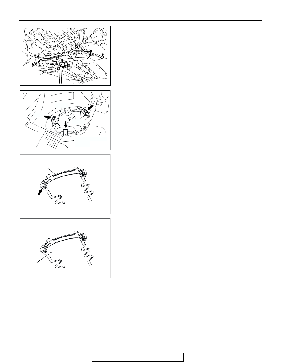
2. Use a transmission jack to lift the crossmember assembly.

3. From inside the vehicle, pull tab A and then tab B to secure 

the three clips to the body panel.
NOTE: 

When securing the steering column dash panel 

cover to the body panel, be careful that the seal lip does not 
move backwards.

4. Check that it has been secured by pressing down the tip of 

the clips by your finger. Also check that the steering column 
dash panel cover is installed securely to the steering gear.

5. After installing the steering column dash panel cover, check 

that the steering column dash panel cover rubber is not 
disengaged from the retainer. If there is any doubt, release 
the clips from the body, engage the rubber again and 
reinstall to the body.

6. Tighten the crossmember mounting nuts and bolts.

.

AC206593

AC306696

TRANSMISSION
JACK

AB

AC306790 AC

ACCELERATOR 
PEDAL

CLIP

TAB A

TAB B

AC308270 AB

SEAL RIP

STEERING COLUMN 
DASH PANEL COVER

AC308270 AC

RUBBER

RETAINER

POWER STEERING GEAR BOX AND LINKAGE

TSB Revision

POWER STEERING

37-39

>>C<< FRONT AXLE CROSSMEMBER 
STAY/SELF-LOCKING NUT INSTALLATION

Ensure that the crossmember mounting bolts have been tight-
ened to 180 

± 20 N⋅m (133 ± 14 ft-lb), and then install the front 

crossmember stay with the self-locking nut.

INSPECTION

M1372011000259

.

STEERING GEAR TOTAL PINION  TORQUE 
CHECK

Required Special Tool:

• MB991006: Preload Socket

CAUTION

• When holding the steering gear in a vice, secure its 

mounting positions. If it is secured in any other place, 
the gear housing may become deformed or damaged.

• Do not loosen the adjust screw more than 2 rotations.
• If the adjust screw is loosened more than 2 rotations, or 

if it is removed, replace the steering gear assembly.

1. Using special tool MB991006, rotate the pinion gear at the 

rate of one rotation in approximately 4 to 6 seconds to check 
the total pinion torque.

Standard value: 0.8 

 1.9 Nm (7.1  16.8 in-lb)

[Change in torque: 0.7 N

m (6.2 in-lb) or less]

NOTE: When measuring, remove the bellows from the rack 
housing. Measure the pinion torque through the whole 
stroke of the rack.

2. If the total pinion torque or the change in torque is outside 

the standard value, loosen the rack support cover once and 
retighten it to the specified torque 12 

± 2 N⋅m (107 ± 17 

in-lb). And then loosen the rack support cover 10 degrees, 
and check the pinion torque again.
If the total pinion torque cannot be adjusted to within the 
standard range by adjusting the rack support cover, replace 
the power steering gear.

.

AC306568 AC

FRONT AXLE 
CROSSMEMBER 
STAY

CROSSMEMBER 
MOUNTING BOLT

SELF-LOCKING NUT

AC306793

MB991006

AB

RACK SUPPORT 
COVER

POWER STEERING GEAR BOX AND LINKAGE

TSB Revision

POWER STEERING

37-40

TIE ROD SWING RESISTANCE CHECK

1. Give 10 hard swings to the tie rod.
2. Measure the tie rod swing resistance with a spring scale.

Standard value:

3.7 

 18.1 N (0.83  4.07 lb) <vehicles with 16-inch 

wheels>

3.6 

 17.8 N (0.81  4.00 lb) <vehicles with 17-inch 

wheels>

[Swing torque: 1.0 

 4.9 Nm (8.9  43.3 in-lb)]

3. If the measured value exceeds the standard value, replace 

the tie rod.

4. If the measured value is below the standard value, the tie 

rod can be re-used if it swings smoothly without excessive 
play.

.

TIE ROD END BALL JOINT DUST COVER CHECK

1. Check the dust cover for cracks or damage by pushing it 

with your finger.

2. If the dust cover is cracked or damaged, replace the tie rod 

end. (Refer to 

P.37-41

).

AC000997

POWER STEERING GEAR BOX AND LINKAGE

TSB Revision

POWER STEERING

37-41

DISASSEMBLY AND ASSEMBLY

M1372011100223

AC307593

1

1312 11

10

9

8

7

6

5

4

3

2

14

15

18

17

16

19

20

2

21

22

23

24

25

26

27

28

29

30

31

32

33

34

36

9

6

2

15

19

2

21

27

28

29

30

33

9

6

17

STEERING GEAR SEAL KIT

NOTE
*: Return the rack support cover - 10˚.

AB

35

59 ± 10 N·m
44 ± 7 ft-lb

22 ± 4 N·m
16 ± 3 ft-lb

13 ± 3 N·m
116 ± 26 in-lb

12 ± 2 N·m*
107 ± 17 in-lb*

25 ± 4 N·m
18 ± 3 ft-lb

84 ± 14 N·m
62 ± 10 ft-lb

52 ± 2 N·m
38 ± 2 ft-lb

59 ± 10 N·m
44 ± 7 ft-lb

13 ± 3 N·m
116 ± 26 in-lb

DISASSEMBLY STEPS

1.

P/S OIL FEED TUBE ASSEMBLY

2.

STEERING GEAR INNER O-RING

>>P<<

3.

STEERING GEAR NUT (TIE ROD 
END JAM NUT)

>>P<<

4.

TIE ROD END ASSEMBLY

5.

STEERING GEAR INNER CLIP

>>O<<

6.

STEERING GEAR BAND (BELLOWS 
BAND)

7.

STEERING GEAR BELLOWS

<<A>>>N<<

8.

STEERING TIE ROD

<<A>>>N<<

9.

STEERING GEAR WASHER (TAB 
WASHER)

>>M<<

TOTAL PINION TORQUE 
ADJUSTMENT

>>L<<

10.

STEERING GEAR INNER NUT (JAM 
NUT)

<<B>>>L<<

11.

STEERING GEAR RACK SUPPORT 
COVER

12.

STEERING GEAR RACK SUPPORT 
SPRING

13.

STEERING GEAR RACK SUPPORT

>>K<<

14.

STEERING GEAR PLUG (END 
PLUG)

15.

STEERING GEAR INNER  NUT

16.

VALVE ASSEMBLY

<<C>>>J<<

17.

OIL SEAL

<<C>>

18.

PINION AND VALVE ASSEMBLY

<<D>>>I<<

19.

SEAL RING

<<E>>>H<<

20.

SPECIAL BEARING

<<E>>>H<<

21.

OIL SEAL

22.

VALVE HOUSING

<<F>> >>G<<

23.

STEERING GEAR PISTON  CLIP 
(CIRCLIP)

24.

STEERING GEAR RACK  STOPPER

>>F<<

25.

STEERING GEAR BUSHING  (RACK 
BUSHING)

<<G>>>E<<

26.

STEERING GEAR RACK

>>D<<

27.

O-RING

<<H>>>D<<

28.

OIL SEAL

29.

PISTON RING

30.

O-RING

<<I>>>C<<

31.

STEERING GEAR PINION  BEARING 
(BALL BEARING)

DISASSEMBLY STEPS  (Continued)


Content   ..  1520  1521  1522  1523   ..