Content .. 1496 1497 1498 1499 ..
Mitsubishi Galant 9G. Manual - part 1498
AIR BAG MODULE AND SEAT BELT PRE-TENSIONER DISPOSAL PROCEDURES
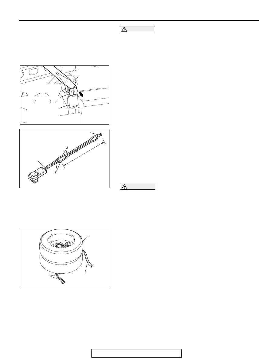
TSB Revision
SUPPLEMENTAL RESTRAINT SYSTEM (SRS)
52B-402
WARNING
Store the seat belt pre-tensioner on a flat surface with
its operation surface facing up. Do not place anything
on top of them.
2. Remove the seat belt pre-tensioner from the vehicle (Refer
3. Use a flat-tip screwdriver to unlock the harness side
connector locking button by withdrawing it toward you in two
stages.
4. Disconnect the D-22 or D-33 harness side connector.
5. Connect two wires, each 6 meters (20 feet) or longer, to the
two leads of special tool pre-tensioner adapter harness
(MB991885), and cover the connections with insulation
tape. The other ends of the two wires should be connected
to each other (short-circuited), to prevent sudden
unexpected operation of the seat belt pre-tensioner.
6. Connect the special tool pre-tensioner adapter harness
(MB991885), which the deployment wires is attached to, to
the seat belt pre-tensioner connector.
CAUTION
The adapter harness below the wheel should be loose. If it
is too tight, the reaction when the seat belt pre-tensioner
operates could damage the adapter harness.
7. Pass the thick wires through the hole on the seat belt
pre-tensioner bracket and secure them to the front (raised
part) of the wheel in two places.
8. Pull the seat belt out to the outside of the tire, and then place
one tire without a wheel on top.
AC103556
D-22 OR D-33
HARNESS SIDE
CONNECTOR
(2-PIN, BLACK)
LOCKING BUTTON
FLAT-TIP SCREW
DRIVER
D-22 OR D-33
SEAT BELT
PRE-TENSIONER
CONNECTOR
(2-PIN)
AR
AC103480
CONNECTION
DEPLOYMENT WIRES
MR991885
INSULATOR TAPE
6 m (20 ft)
LONG OR
MORE
AC
AC303963
TIRES
WITHOUT
WHEELS
AB
SEAT BELT
DEPLOYMENT
WIRES