Mitsubishi Galant 9G. Manual - part 1321


  Index      Mitsubishi     Mitsubishi Galant 9G - service repair manual


Search            


Content   ..  1319  1320  1321  1322   ..


Mitsubishi Galant 9G. Manual - part 1321


DIAGNOSIS

TSB Revision

CONTROLLER AREA NETWORK (CAN)

54C-388

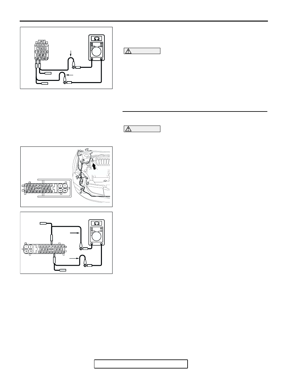
(4) Measure the resistance between powertrain control module 

connector terminals 17 and 18.

OK: 1 k

 or more

CAUTION

Strictly observe the specified wiring harness repair proce-
dure. For details refer to 

P.54C-5

.

Q: Does the resistance measure 1 k

 or more?

YES : If the resistance measures 1 k

Ω or more, go to Step 

34  .

NO :  If the resistance measures less than 1 k

Ω, repair the 

wiring harness between powertrain control module 
connector and ABS-ECU connector.

STEP 34. Check the ABS-ECU for short circuit. Measure 
the resistance at ABS-ECU connector A-02.

CAUTION

A digital multimeter should be used. For details refer to 

P.54C-4

.

(1) Disconnect ABS-ECU connector A-02, and measure the 

resistance at the component side of ABS-ECU connector 
A-02.

(2) Measure the resistance between ABS-ECU connector 

terminals 7 and 25.

OK: 1 k

 or more

Q: Does the resistance measure 1 k

 or more?

YES : If the resistance measures 1 k

Ω or more, go to Step 

35  .

NO :  If the resistance measures less than 1 k

Ω, replace the 

ABS-ECU.

AC209438

AC209438

AC209438

HARNESS SIDE: B-19

BC

TEST 
HARNESS

TEST 
HARNESS

AC305206

CONNECTOR: A-02

AG

A-02 (GR)

HARNESS SIDE

AC209438

COMPONENT SIDE: A-02

TEST 
HARNESS

AB

TEST 
HARNESS

DIAGNOSIS

TSB Revision

CONTROLLER AREA NETWORK (CAN)

54C-389

STEP 35. Check the powertrain control module for short 
circuit. Measure the resistance at powertrain control 
module connector B-19.

CAUTION

A digital multimeter should be used. For details refer to 

P.54C-4

.

(1) Disconnect powertrain control module connector B-19, and 

measure the resistance at the component side of 
powertrain control module connector B-19.

(2) Measure the resistance between powertrain control module 

connector terminals 17 and 18.

OK: 120 

± 20 

Q: Does the resistance measure 120 

± 20 ?

YES : If the resistance measures 120 

± 20 Ω, diagnose CAN 

bus lines thoroughly by referring to 

P.54C-520

.

NO :  If the resistance does not measure 120 

± 20 Ω, 

replace the powertrain control module.

AC306248AD

B-19 (B)

CONNECTOR: B-19

PCM

AIR
CLEANER

HARNESS SIDE

AC209438

AC209438

AC209438

AC209438

COMPONENT SIDE: B-19

BD

TEST 
HARNESS

TEST 
HARNESS

NEXT>>

DIAGNOSIS

TSB Revision

CONTROLLER AREA NETWORK (CAN)

54C-390

54C

DIAGNOSTIC ITEM 10: Diagnose terminator resistors at both ends <Vehicles without ABS>

CAUTION

When servicing a CAN bus line, ground yourself 
by touching a metal object such as an unpainted 
water pipe. If you fail to do so, a component con-
nected to the CAN bus line may be damaged.

.

POWERTRAIN
CONTROL MODULE

JOINT
CONNECTOR (3)

COMBINATION
METER

AC306248AB

B-19 (B)

CONNECTOR: B-19

AIR
CLEANER

PCM

AC305231CA

C-101

C-29

C-02

CONNECTORS: C-02, C-29, C-101

<<PREVIOUS

DIAGNOSIS

TSB Revision

CONTROLLER AREA NETWORK (CAN)

54C-391

TROUBLE JUDGMENT

The terminator resistors at both ends of CAN bus 
lines may be damaged, when the resistance 
between the CAN bus lines (CAN_L and H lines) is 
more than 2 ohms.

.

COMMENTS ON TROUBLE SYMPTOM

The CAN bus line harness wires or connectors may 
be damaged (open circuit may be present on CAN_L 
or CAN_H line between the data link connector and 
CAN main bus lines, or CAN main bus lines may be 
open at both sides), or the combination meter and 
the powertrain control module may be defective. 

.

TROUBLESHOOTING HINTS

• The wiring harness or connectors may have 

loose, corroded, or damaged terminals, or termi-
nals pushed back in the connector

• The combination meter may be defective

• The powertrain control module may be defective

DIAGNOSIS

Required Special Tool:

• MB991223: Harness Set

STEP 1. Check intermediate connector C-29 for loose, 
corroded or damaged terminals, or terminals pushed back 
in the connector.

CAUTION

The strand end of the twisted wire should be within 10 cm 
(4 inches) from the connector. For details refer to 

P.54C-4

.

Q: Is intermediate connector C-29 in good condition?

YES : Go to Step 2.
NO :  Repair the damaged parts.

AC305231AI

CONNECTOR: C-29


Content   ..  1319  1320  1321  1322   ..