Mitsubishi Evolution X. Manual - part 242
 

  Index      Mitsubishi     Mitsubishi Evolution X - service repair manual 2008 year


Search            


Content   ..  240  241  242  243   ..


Mitsubishi Evolution X. Manual - part 242


AK304677

CHARGING SYSTEM

TSB Revision

ENGINE ELECTRICAL

16-21

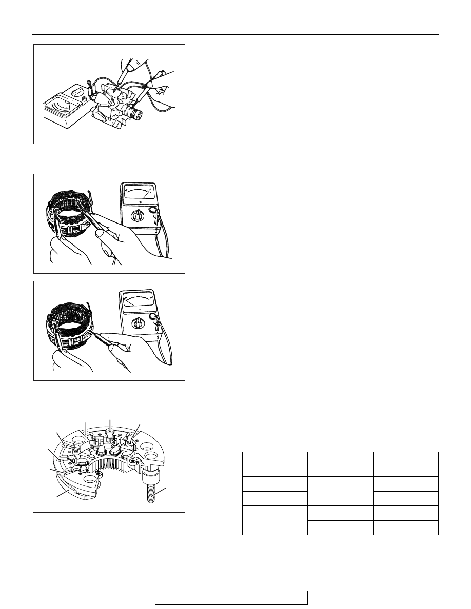
3. If continuity is present, replace the rotor.

.

STATOR

AK304678

1. Check the continuity between coil leads.

If there is no continuity, replace the stator.

AK304679

2. Check the continuity between coil and core.

If there is continuity, replace the stator.

.

RECTIFIER ASSEMBLY

AK703436

E

AC

B

P6

P4

P5

P3

P2

P1

Use the analog type tester to make sure the electrical continuity 
of each diode meets the table. 
Unless the electrical continuity of each diode meets the table, 
replace the rectifier.

(

) side

(+) side

Electrical 
continuity

E

P1, P2, P3, P4, 
P5, P6

Yes

B

No

P1, P2, P3, P4, 
P5, P6

E

No

B

Yes

.

CHARGING SYSTEM

TSB Revision

ENGINE ELECTRICAL

16-22

BRUSH

AK703437AC

Protrusion
length

1. Measure the length of the protrusion of the brush. Replace 

the brush if the protrusion length is shorter than the limit.

Limit: 2 mm (0.1 inch) minimum

2. Unsolder the lead of the brush. The brush will come out, 

becoming ready for removal.

AK703438AC

Solder

3. Install a new brush by pushing it into the holder as shown in 

the drawing and soldering the lead.

STARTING SYSTEM

TSB Revision

ENGINE ELECTRICAL

16-23

STARTING SYSTEM

GENERAL INFORMATION

M1161000101309

If the ignition switch is turned to the "START" posi-
tion, current flows in the coil provided inside mag-
netic switch, attracting the plunger. When the plunger 
is attracted, the lever connected to the plunger is 
actuated to engage the starter clutch.
On the other hand, attracting the plunger will turn on 
the magnetic switch, allowing the "B" terminal and 
"M" terminal to conduct. Thus, current flows to 
engage the starter motor.

When the ignition switch is returned to the "ON" posi-
tion after starting the engine, the starter clutch is dis-
engaged from the ring gear.
An overrunning clutch is provided between the pinion 
and the armature shaft, to prevent damage to the 
starter.

AK604152

Pull-in coil

Holding coil

Plunger

Lever

Pinion gear

Overrunning clutch

Yoke

Brush

Armature

Ignition switch - ST

ECM

Starter relay

Battery

+

AB

B

M

S

OPERATION

For models equipped with TC-SST, when the ignition 
switch is turned to the "ST" position while the selec-
tor lever is at the "P" or "N" position, the contact 
(magnetic switch) of the starter is switched ON and 
the starter motor is activated.

STARTING SYSTEM

TSB Revision

ENGINE ELECTRICAL

16-24

GENERAL SPECIFICATIONS

M1162000200083

ITEMS

M/T

TC-SST

Type

Reduction drive with planetary gear

Identification number

M000T21571

M000T22871

Part No.

1810A011

1810A123

Rated output kW/V

1.4/12

Number of pinion teeth

8

9

SERVICE SPECIFICATIONS

M1162000300466

ITEMS

STANDARD VALUE

LIMIT

Free running 
characteristics

Terminal voltage V 11

Current A

90

Speed r/min

2,000 or more <M/T>
2,400 or more <TC-SST>

Pinion gap mm (in)

0.5 

− 2.0 (0.02 − 0.07)

Commutator run-out mm (in)

0.05 (0.002)

Minimum 0.1 (0.004)

Commutator diameter mm (in)

29.4 (1.16)

Minimum 28.8 (1.13)

Undercut depth mm (in)

0.5 (0.02)

Minimum 0.2 (0.008)

STARTING SYSTEM DIAGNOSIS

M1162000700497

TROUBLESHOOTING HINTS

The starter motor does not operate at all.

WARNING

Battery posts, terminals and related accessories con-
tain lead and lead compounds. WASH HANDS AFTER 
HANDLING.

• Check the starter (coil).

• Check for poor contact at the battery terminals and 

starter.

• Check the transmission range switch.

The starter motor doesn't stop

• Check the starter (magnetic switch).


Content   ..  240  241  242  243   ..