Mitsubishi Evolution X. Manual - part 1093


  Index      Mitsubishi     Mitsubishi Evolution X - service repair manual 2008 year


Search            


Content   ..  1091  1092  1093  1094   ..


Mitsubishi Evolution X. Manual - part 1093


SERVICE PRECAUTIONS

TSB Revision

CONTROLLER AREA NETWORK (CAN)

54C-7

SERVICE PRECAUTIONS

M1548302100258

Warnings in diagnosis section

Details regarding warnings

CAUTION

When servicing a CAN bus line, ground yourself 
by touching a metal object such as an unpainted 
water pipe. If you fail to do, a component 
connected to the CAN bus line may be broken.

CAUTION

A digital multimeter should be used.

When measuring resistance value or voltage in 
CAN bus lines, use a digital multimeter. If not 
using a digital multimeter, the equipments, which 
are connected through the CAN communication 
lines, may be damaged.

CAUTION

When measuring the resistance, disconnect the 
negative battery terminal.

Disconnect the negative battery terminal when 
measuring the resistance value in the CAN bus 
line. If you fail to do so, the equipments, which 
are connected through the CAN communication 
lines, may be damaged.

CAUTION

The test wiring harness should be used.

Always use the test harness when measuring the 
voltage or resistance value at the female 
connector. If you fail to do so, connectors may be 
damaged.

CAUTION

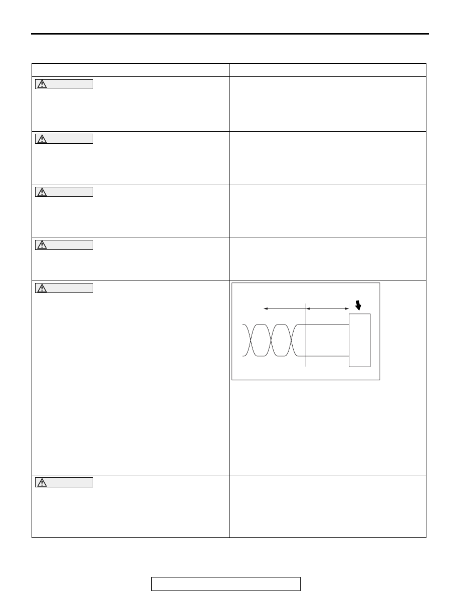
The strand end of the twist wire should be within 
10 cm from the connector.

If you repair the wire due to a defective 
connector or its terminal or harness wire, you 
should cut the wire so that the strand end of the 
twist wire should be within 10 cm (4 inches) from 
the connector as shown. If it exceeds 10 cm (4 
inches), twist the wiring harness just like the 
original twisted wire. If the strand end exceeds 
10 cm (4 inches), a communication error may be 
caused.

CAUTION

Strictly observe the specified wiring harness 
repair procedure.

When you repair a CAN bus line, observe the 
precautions on how to repair the CAN bus line 
strictly. Refer to 

P.54C-8

. If a new wire is added 

or a splice point is modified for the CAN_L or 
CAN_H line, an error in the CAN communication 
may be caused.

AC203824

Connector

Twisted wire

AF

10 cm
 (4.0 inches)

PRECAUTIONS ON HOW TO REPAIR THE CAN BUS LINES

TSB Revision

CONTROLLER AREA NETWORK (CAN)

54C-8

PRECAUTIONS ON HOW TO REPAIR THE CAN BUS LINES

M1548301900251

.

PRECAUTIONS ON HOW TO REPAIR THE CAN 
BUS LINES

• If the CAN bus line(s) are repaired, renew all the twisted 

wires between the end connectors. If the wiring harness is 
partially repaired, or only CAN_L or CAN_H line is repaired, 
noise suppression is deteriorated, causing a communica-
tion error.

• If the connector or wire on the main bus line or the sub-bus 

wire is replaced, the frayed end of the twisted wire should 
be within 10 cm (4 inches) from the connector. If it exceeds 
10 cm (4 inches), twist the wiring harness just like the origi-
nal twisted wire. If the frayed end exceeds 10 cm (4 inches), 
noise suppression is deteriorated, causing a communica-
tion error.

• If a sub-bus line is repaired, splice a new wire directly into 

the main bus line. If a new wire is spliced into the sub-bus 
line, which is connected to another device, the CAN com-
munication will be disabled.

.

AC204696

Added wire

No good

AD

AC203824

Connector

Twisted wire

AF

10 cm
 (4.0 inches)

AC202856

ECU

ECU

ECU

ECU

Good

No good

Terminator resistor

Open
circuit
point

Terminator resistor

AE

Open
circuit
point

EXPLANATION ABOUT THE SCAN TOOL (M.U.T.-III) CAN BUS DIAGNOSTICS

TSB Revision

CONTROLLER AREA NETWORK (CAN)

54C-9

PRECAUTIONS ON HOW TO REPAIR THE 
TERMINATOR RESISTOR

If one-side terminator resistor is broken, the CAN 
communication will continue although noise suppres-
sion is deteriorated. No diagnostic trouble code may 
be set even if the terminator resistor was broken. If a 
damage is found, replace the ECU which incorpo-
rates the defective terminator resistor.

EXPLANATION ABOUT THE SCAN TOOL (M.U.T.-III) 

CAN BUS DIAGNOSTICS

M1548300100490

Scan tool MB991958 CAN bus diagnostics carries 
out the two checks below automatically, and then dis-
plays current condition of the CAN bus lines accord-
ing to the check results.

CAN BUS LINE DIAGNOSTIC FLOW

1. Scan tool CAN bus diagnostics

Scan tool MB991958 diagnoses CAN bus lines in 
accordance with the following strategy.
NOTE: After you determine whether the CAN-C 
lines are in good condition, then determine 
whether the CAN-B lines are in good condition. 
Then confirm each judgement result on the scan 
tool screen.

(1) Check that the ETACS-ECU sets a diagnostic 

trouble code.
You can narrow down the points to be 
diagnosed by confirming an ETACS-ECU 
diagnostic trouble code.

(2) Checking the communication condition of 

ECUs
Scan tool MB991958 narrows down troubles in 
circuit by itself. Its strategies are as follows.

AC507612 AB

(1) Check that the etacs-ecu sets a diagnosis code.

NO

NG

YES

From other diagnosis

1. Scan tool MB991958
    (M.U.T.-III) CAN bus
    diagnostics

Go to ordinary diagnosis

OK for (2)
P code, B code, 
C code or 
U code (current trouble)

OK for (2) 
U code (past trouble)

2. Pinpoint possible trouble spot 
    according to diagnosis code

· Open circuit in CAN bus line
· Broken terminator resistor
· Power supply to ecu poorly grounded

Short in CAN bus line to power 
supply or ground

(2) Checking the communication condition of ecus.

EXPLANATION ABOUT THE SCAN TOOL (M.U.T.-III) CAN BUS DIAGNOSTICS

TSB Revision

CONTROLLER AREA NETWORK (CAN)

54C-10

AC204741

ECU B

ECU C

ECU D

ECU A

(a)

(b)

(c)

(h)

(d)

(e)

(f)

(g)

AD

ETACS-ECU
(Gateway)

Reference circuit

Data link 
connector

ECU which 
cannot 
communicate 
with the scan 
tool

Possible 
trouble spot

Logic for narrowing down trouble spot

ETACS-ECU 
and all ECUs

CAN bus line 
(h) and power 
supply 
system to 
ETACS-ECU

The ETACS-ECU and the other 
ECUs use the CAN bus line (h) 
when they communicate with 
scan tool MB991958. Since 
none of the ETACS-ECU and 
the other ECUs can 
communicate with scan tool 
MB991958, CAN bus line (h) or 
the power supply circuit to the 
ETACS-ECU may be faulty.

ECU A

CAN bus line 
(a) and power 
supply 
system to 
ECU A

ECU A communicates with the 
scan tool MB991958 via CAN 
bus lines (a) and (b). Scan tool 
MB991958 judges that CAN 
bus line (b) is normal, because 
it can communicate with other 
ECUs. Possible trouble may be 
present in CAN bus line (a) or 
the power supply system to 
ECU A.

AC204742BO

ECU B

ECU C

ECU D

ECU A

(a)

(b)

(c)

(d)

(e)

(f)

(g)

(h)

ETACS-ECU
(Gateway)

Data link 
connector

AC204742BH

ECU B

ECU C

ECU D

ECU A

(a)

(b)

(c)

(d)

(e)

(f)

(g)

(h)

ETACS-ECU
(Gateway)

Data link 
connector


Content   ..  1091  1092  1093  1094   ..