Mitsubishi Lancer Evolution X. Manual - part 6


  Index      Mitsubishi     Mitsubishi Lancer Evolution X GS41EVO - service repair manual 2008 year


Search            


Content   ..  4  5  6  7   ..


Mitsubishi Lancer Evolution X. Manual - part 6


DIAGNOSIS

TSB Revision

CONTROLLER AREA NETWORK (CAN)

54C-49

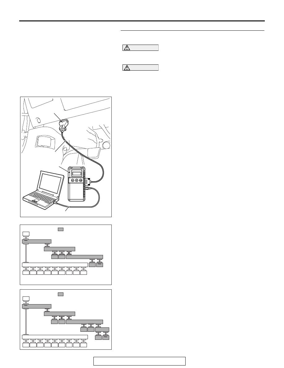
STEP 17. Using scan tool MB991958, diagnose the CAN 
bus line. (checking the TC-SST-ECU for internal short)

CAUTION

Strictly observe the specified wiring harness repair proce-
dure. For details refer to 

P.54C-7

.

CAUTION

To prevent damage to scan tool MB991958, always turn the 
ignition switch to the "LOCK" (OFF) position before con-
necting or disconnecting scan tool MB991958.
(1) Disconnect transaxle assembly connector B-107.
(2) Connect scan tool MB991958 to the data link connector.
(3) Turn the ignition switch to the "ON" position.

(4) Diagnose CAN bus lines, and check if the scan tool 

MB991958 screen is as shown in the figure.

OK: The display of the scan tool MB991958 is as 
shown in the figure.

Q: Does scan tool MB991958 screen correspond to the 

illustration?
YES : 
Repair the wiring harness between transaxle 

assembly connector B-107 and joint connector 
(CAN4) A-14.

NO :  Check transaxle assembly connector B-107, and 

repair if necessary. If the transaxle assembly 
connector is in good condition, replace the transaxle 
assembly

AC608435

Data link connector

MB991827

MB991824

MB991910

AB

AC709542 AC

: Red section on screen

M.U.T.

J/C (3)

J/C (2)

KOS/WCM

SRS

A/C

AUDIO

MMCS

Sat Radio

HFM

OCM

METER

ASC

ENGINE

J/C (1)

ETACS

<M/T>

SAS

S-AWC

AC709543 AC

: Red section on screen

M.U.T.

J/C (3)

J/C (2)

KOS/WCM

SRS

A/C

AUDIO

MMCS

Sat Radio

HFM

OCM

METER

ASC

LEVER

J/C (1)

ETACS

<TC-SST>

SAS

S-AWC

J/C (4)

TC-SST

ENGINE

DIAGNOSIS

TSB Revision

CONTROLLER AREA NETWORK (CAN)

54C-50

STEP 18. Using scan tool MB991958, diagnose the CAN 
bus line.

CAUTION

To prevent damage to scan tool MB991958, always turn the 
ignition switch to the "LOCK" (OFF) position before con-
necting or disconnecting scan tool MB991958.
(1) Connect scan tool MB991958 to the data link connector.
(2) Turn the ignition switch to the "ON" position.

(3) Diagnose CAN bus lines, and check if the scan tool screen 

is as shown in the illustration.

Q: Does the scan tool screen correspond to the 

illustration?
YES : 
The trouble can be an intermittent malfunction (Refer 

to GROUP 00, How to use 
Troubleshooting/inspection Service Points − How to 

Cope with Intermittent Malfunction 

P.00-15

).

NO :  Check ETACS-ECU connector C-301, and repair if 

necessary. If the ETACS-ECU connector is in good 
condition, replace the ETACS-ECU.

AC608435

Data link connector

MB991827

MB991824

MB991910

AB

AC709542 AB

: Red section on screen

M.U.T.

J/C (3)

SAS

J/C (2)

KOS/WCM

SRS

A/C

AUDIO

MMCS

Sat Radio

HFM

OCM

METER

ASC

ENGINE

J/C (1)

ETACS

<M/T>

S-AWC

AC709543 AB

: Red section on screen

M.U.T.

J/C (3)

SAS

J/C (2)

KOS/WCM

SRS

A/C

AUDIO

MMCS

Sat Radio

HFM

OCM

METER

ASC

LEVER

ENGINE

J/C (1)

ETACS

<TC-SST>

S-AWC

TC-SST

J/C (4)

DIAGNOSIS

TSB Revision

CONTROLLER AREA NETWORK (CAN)

54C-51

DIAGNOSTIC ITEM 4: Diagnose shorts in the ground to CAN-C bus line.

CAN-C Communication Circuit <M/T>

ETACS-ECU

INTERFACE 
CIRCUIT

CAN DRIVE 
CIRCUIT

JOINT CONNECTOR 
(CAN2)

JOINT CONNECTOR 
(CAN3)

ASC-ECU

STEERING 
WHEEL SENSOR

AWC-ECU

ENGINE CONTROL 
MODULE

DIAGNOSIS

TSB Revision

CONTROLLER AREA NETWORK (CAN)

54C-52

TRANSAXLE 
ASSEMBLY

ENGINE CONTROL MODULE

CAN-C Communication Circuit <TC-SST>

ETACS-ECU

INTERFACE 
CIRCUIT

CAN DRIVE 
CIRCUIT

JOINT CONNECTOR 
(CAN2)

JOINT CONNECTOR 
(CAN3)

JOINT CONNECTOR 
(CAN4)

SHIFT LEVER

ASC-ECU

STEERING 
WHEEL SENSOR

AWC-ECU

NOTE

: THE TERMINAL NUMBERS DESCRIBED 

IN THE CIRCUIT DIAGRAM AGREE WITH 
THE NUMBERS MARKED ON THE 
TRANSAXLE ASSEMBLY CONNECTOR AND 
HARNESS SIDE CONNECTOR.


Content   ..  4  5  6  7   ..